Preparing for flushing
CAUTION:
Refrigerant circuit under high pressure.
Injury hazard!
Injury hazard!
- Note and follow the manufacturer safety instructions on containers.
- Avoid contact with refrigerant; wear safety goggles and hand protection.
- For additional information see: 64 50 HANDLING REFRIGERANT and 64 50 NOTES on air conditioning repair work
Preliminary work
- Suction the AIR CONDITIONING .
- Remove the acoustic COVER .
- Remove intake silencer HOUSING .
- Remove the top engine compartment COVER .
- Remove the top right engine compartment COVER .
- Remove the left and right FRONT-END STRUT
- Remove front CROSS CONNECTION .
- Remove the rear top CROSS CONNECTION .
- Remove fan COWL .
- Remove the front left and right WHEELS .
- Remove the front UNDERBODY PROTECTION/FRONT THRUST FIELD .
- Remove the UNDERBODY PROTECTION of the steering gear and thrust field respectively.
- Remove the STIFFENING PLATE .
- Release the front axle support ANTI-ROLL BAR
- If installed: release the active STABILIZER (additional work for ARS).
- Release the tie rod on the left and right from the SWIVEL BEARING .
- Remove UNIVERSAL JOINT .
- Remove the STEERING GEAR .
- Remove air conditioning COMPRESSOR .
- Remove EXPANSION VALVE .
NOTE:
RISK OF DAMAGE External damage to air conditioning compressor. Excessive force applied during removal will result in damage to the air conditioning compressor.
- Remove the air conditioning compressor without damaging it and without applying external force.
- Avoid impacts/knocks to plastic belt pulley (caused by tools, contact with base).
- Return faulty air conditioning compressors in their original packaging only.
NOTE:
TECHNICAL INFORMATION
Vehicle programing/coding must be performed after installation.
For additional information see: 61 00... PROGRAMING/ENCODING control unit(s)
Vehicle programing/coding must be performed after installation.
For additional information see: 61 00... PROGRAMING/ENCODING control unit(s)
NOTE:
TECHNICAL INFORMATION
Perform WHEEL ALIGNMENT after installation.
Perform WHEEL ALIGNMENT after installation.
NOTE:
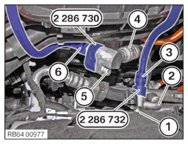
Schematic diagram is for example purposes. Some parts may differ in certain details.
- Guide the high pressure line (2) and low pressure line (4) out and upwards.
- Mount the special tool 2 286 732
on the high pressure line (2) of the air conditioning compressor and secure with the screw (1) on the side of vehicle.
- Mount the special tool 2 286 730
on the low pressure line (4) of the air conditioning compressor and secure with the screw (5) on the side of vehicle.TIGHTENING TORQUES SPECIFICATION
Refrigerant line on air conditioning compressor M8 Tightening torque 19 Nm - Preparing the connection to the A/C service station:
- Connect the high pressure line of the A/C service station (3) to the high-pressure connection of the special tool 2 286 732 .
- Connect the low pressure line of the A/C service station (6) to the low pressure connection of the special tool 2 286 730 .
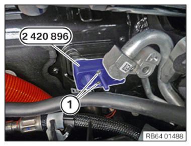
- Mount the special tool 2 420 896 instead of expansion valve 1 as shown and secure with the screws (1) of the expansion valve that were removed earlier.
- Tighten the screws (1).TIGHTENING TORQUES SPECIFICATION
Expansion valve to heater - A/C M5 Tightening torque 5.5 Nm - Position the refrigerant line (1) on the special tool 2 420 896 .
- Use the nuts (2) of the expansion valve that were removed earlier for mounting.
- Tighten nut (2).TIGHTENING TORQUES SPECIFICATION
Refrigerant line to expansion valve/connecting piece M6 Tightening torque 13 Nm - Position the refrigerant lines (3) for the high-voltage battery unit.
- Tighten the screws (4).
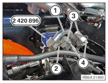
TIGHTENING TORQUES SPECIFICATION
| Refrigerant line to expansion valve/connecting piece | ||
| M6 | Tightening torque | 13 Nm |