If necessary: Replacing the piston
CAUTION:
Spring preload.
Injury hazard!
Injury hazard!
- The use of the specified special tool (tool) is mandatory.
- Carry out the described steps properly.
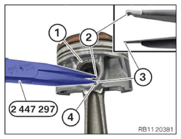
- Use the special tool 2 447 297 to remove the piston pin circlip.
- Insert the flat side (3) of the special tool in the groove (4).
- Use the curved side (2) to grip and remove the piston pin circlip (1).
NOTE:
TECHNICAL INFORMATION
Piston and piston pin are matched to each other.
Always install piston and piston pin together and do not switch by mistake.
Piston and piston pin are matched to each other.
Always install piston and piston pin together and do not switch by mistake.
- Remove the piston pin (1) in arrow direction.
- Remove the piston (2) from the connecting rod (3).
- Replace piston with gudgeon pin.
Parts : Pistons
NOTE:
TECHNICAL INFORMATION
Piston and piston pin are matched to each other.
Always install piston and piston pin together and do not switch by mistake.
Piston and piston pin are matched to each other.
Always install piston and piston pin together and do not switch by mistake.
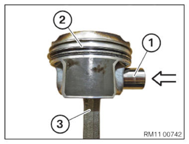
- Position piston (2) on the connecting rod (3).
- Install the piston pin (1) in arrow direction.
- Must be able to install the piston pin (1) without the use of excessive force.
- The piston pin (1) must be in the piston and the connecting rod free of play.
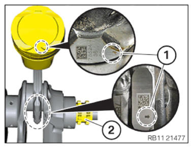
- The arrows (1) on the piston and connecting rod bearing cap must point in the driving direction to the timing chain drive (2) for installation in the crankcase.
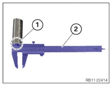
- Determine the inner dimension of the piston pin boss (1) with a standard caliper gauge (2).
INNER DIMENSION OF PISTON PIN BOSS SPECIFICATION
| Engine | N63B44T3 | N63B44T3 |
|---|---|---|
| Inner dimension of piston pin boss | 10.8 mm to 11.1 mm | 10.3 mm to 10.6 mm |
| Special tool | 2450210 | 2471299B |
| Diameter of special tool | Ø 10.75 mm | Ø 10.25 mm |
| Key range | 10 mm | 8 mm |
| Engine | N63B44M3/S63B44T4 | N63B44M3/S63B44T4 |
|---|---|---|
| Inner dimension of piston pin boss | 10.8 mm to 11.1 mm | 11.3 mm to 11.6 mm |
| Special tool | 2450210 | 2471299 A |
| Diameter of special tool | Ø 10.75 mm | Ø 11.25 mm |
| Key range | 10 mm | 10 mm |
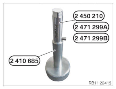
- Prepare special tool 2 450 210 /2471299 A/2471299 B on the installation aid 2 410 685 .
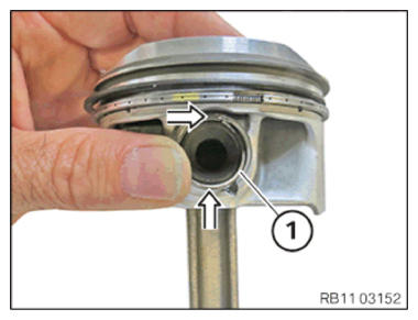
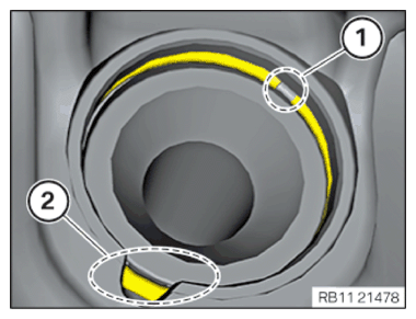
- Insert the piston pin circlip (1) in the groove on the piston (see arrows).
- Screw in the positioned piston pin circlip (2) with 2 410 685 and 2 450 210 /
2471299 A/2471299 B with the guide pin (1) in arrow direction.
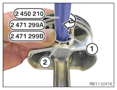
- Screw the piston pin circlip with the guide pin (1) into the groove of the piston in arrow direction.
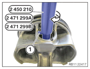
- The piston pin circlip must fit correctly in the groove.
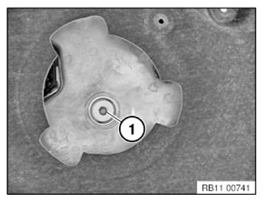
- The opening (1) on the piston pin circlip must be against the recess on the piston.
If necessary: Remounting piston rings
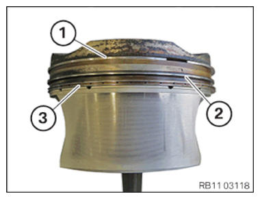
- Check the arrangement of the piston rings.
Piston ring (1.)
Piston ring (2).
Oil scraper ring (3).
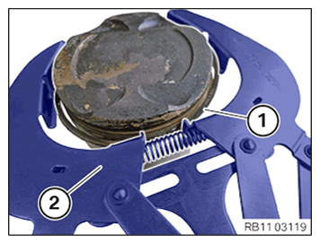
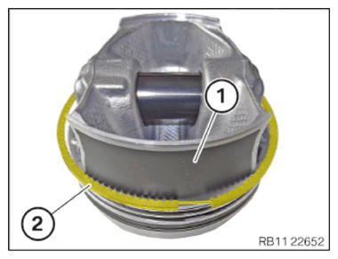
- Remove upper and middle piston ring (1) with a piston ring pliers (2).
- Remove oil scraper ring (2) (U-Flex) by hand over the piston skirt (1).
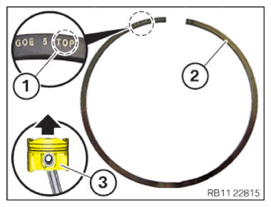
- The TOP mark (1) on the piston rings (2) must be installed at the piston roof of the piston (3).
- Install oil scraper ring (2) (U-Flex) by hand over the piston skirt (1) Install.

- Install upper and middle piston ring (1) with a piston ring pliers (2).