Installing wiring harness section for ignition system of bank 2
Wiring harness section for the ignition system of cylinder bank 2
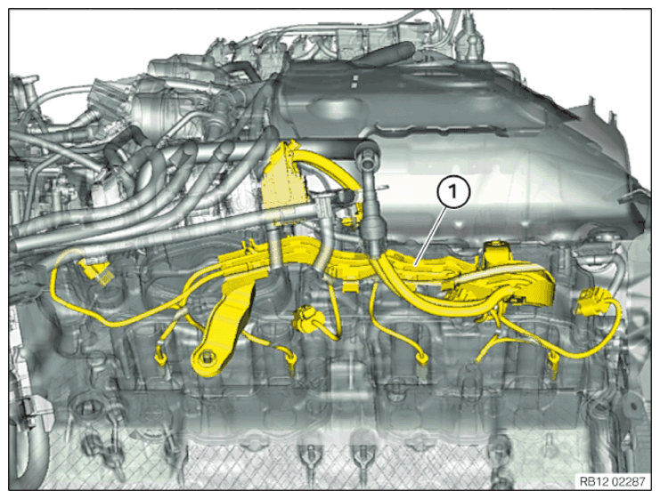
- Feed in and position the wiring harness section for the ignition system of cylinder bank (2).
- Position ground cable (2).
- Tighten nuts (1).
TIGHTENING TORQUES SPECIFICATION
| Ground cable to hold-down device | ||
| Nuts | Tightening torque | 5.5 Nm |
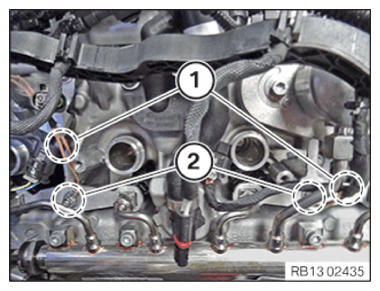
NOTE:
Schematic diagram is for example purposes. Some parts may differ in certain details.
- Check all connectors (1) on the injectors again to ensure they are correctly fitted.
- Check that all connectors are plugged in correctly.
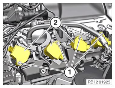
→ Install the ignition coils of cylinder bank
Prerequisite
Ignition is switched off.
NOTE:
RISK OF DAMAGE
Damage to the ignition coil.
The silicone hose of the ignition coil must not be contaminated by fuel as this can lead to failure of the ignition coil.
Damage to the ignition coil.
The silicone hose of the ignition coil must not be contaminated by fuel as this can lead to failure of the ignition coil.
- When working on the fuel system, cover the ignition coils with suitable materials and remove where required.
- Do not oil or grease the silicone tube of the spark plug socket. Do not use any protection or maintenance products (e.g. silicone spray, rubber care products, rust remover, etc.).
- Feed in the ignition coils (2) and install them.
- Tighten the screws (1).
TIGHTENING TORQUES SPECIFICATION
| Ignition coil | ||
| screw | Tightening torque | 8 Nm |
- Feed in and install the cable clip (3).
- Tighten down screw (2).
TIGHTENING TORQUES SPECIFICATION
| Wiring harness on the cylinder head cover | ||
| M6x16 screw | Tightening torque | 10 Nm |
| Nut M6 | Tightening torque | 10 Nm |
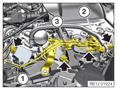
- Tighten nut (1).
TIGHTENING TORQUES SPECIFICATION
| Wiring harness on the cylinder head cover | ||
| M6x16 screw | Tightening torque | 10 Nm |
| Nut M6 | Tightening torque | 10 Nm |
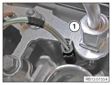
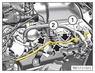
- Connect and lock connectors (arrows).
The connectors (arrows) must audibly engage.
- Feed the cable (2) into the bracket (arrows).
- Secure clamps (1).
Follow-up work
- Refer to INSTALLING COOLANT EXPANSION TANK .
- Refer to INSTALLING THE CONTROL UNIT BRACKET FOR CYLINDERS 5 TO 8 .
- Refer to INSTALLING CLEAN AIR PIPE, TOP .
- Refer to INSTALLING THE COVER OF THE LEFT DME CONTROL UNIT .
- Refer to INSTALLING CONTROL UNIT HOLDER FOR CYLINDERS 1 TO 4 .
- Refer to CONNECTING NEGATIVE BATTERY CABLE .