Removing the steering gear
NOTE:
TECHNICAL INFORMATION
In a warranty case, you must always provide a fault memory printout with the defective part, even if the fault memory does not contain an entry.
In a warranty case, you must always provide a fault memory printout with the defective part, even if the fault memory does not contain an entry.
NOTE:
TECHNICAL INFORMATION
Perform WHEEL ALIGNMENT after installation.
Perform WHEEL ALIGNMENT after installation.
NOTE:
TECHNICAL INFORMATION
Vehicle programing/coding must be performed after installation.
For additional information see: 61 00... PROGRAMING/ENCODING control unit(s)
Vehicle programing/coding must be performed after installation.
For additional information see: 61 00... PROGRAMING/ENCODING control unit(s)
Preliminary work
- Remove the front left and right WHEELS .
- Remove the UNDERBODY PROTECTION of the steering gear and thrust field respectively.
- Remove the STIFFENING PLATE .
- Remove both TRACK END RODS
- Remove the steering gear UNIVERSAL JOINT .
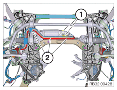
- Disconnect connector (1).
Carefully unclip the cable duct (2) from the front subframe with a screwdriver and set it aside.
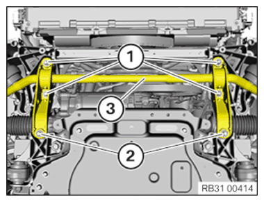
Release the anti-roll bar from the front axle support
- Release screws (1) and (2) from the holder of the anti-roll bar (3) on the front axle support.
- Remove anti-roll bar (3).
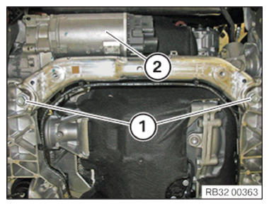
- Undo screws (1) and remove steering gear (2) toward the bottom.