Removing the wiring harness section for sensor system 1
WARNING:
Working on 12 V electrical system.
Risk of short circuits! Risk of fire!
Risk of short circuits! Risk of fire!
- Make sure that there is no charger connected to the jump start terminal in the engine compartment.
- Detach battery ground lead from battery.
- For auxiliary batteries: Detach battery minus cables from all auxiliary batteries.
Preliminary work
- Refer to DISCONNECTING ALL BATTERY GROUND LEADS .
- Refer to REMOVING THE SEAL FOR THE HOOD REAR .
- Refer to REMOVING THE ACOUSTIC COVER .
- Refer to REMOVING ACOUSTIC COVER AT REAR .
- Refer to REMOVING THE COVER ON LEFT AND RIGHT IN THE ENGINE COMPARTMENT AT THE TOP .
- Refer to REMOVING FRONT CROSS CONNECTION .
- Refer to REMOVING THE REAR TOP CROSS CONNECTION .
- Refer to REMOVING THE FAN COWL .
- Refer to DETACHING THE CHARGE AIR LINE FROM THE THROTTLE BODY .
- Refer to REMOVE TANK VENT VALVE .
- Refer to REMOVING THE DME CONTROL UNIT .
- Refer to REMOVING THE INTEGRATED POWER SUPPLY MODULE (PDM) .
- Refer to REMOVING CONTROL UNIT BRACKET .
- Refer to REMOVING THE FRONT UNDERBODY PROTECTION OR FRONT THRUST FIELD .
- Refer to REMOVING THE UNDERBODY PROTECTION OF THE STEERING GEAR AND THRUST FIELD RESPECTIVELY .
- Refer to REMOVING THE STIFFENING PLATE .
- Refer to REMOVING THE UNDERBODY PLANKING OF THE TRANSMISSION ON THE SIDE .
- Refer to REMOVING REAR UNDERBODY PROTECTION .
- Refer to PARTIALLY RELEASE ACOUSTIC COVER OF OIL SUMP .
- Refer to DRAINING THE COOLANT FROM THE LOW-TEMPERATURE COOLING SYSTEM .
- Refer to DRAINING THE COOLANT FROM THE HIGH-TEMPERATURE COOLING SYSTEM .
- Refer to REMOVING TRANSMISSION OIL COOLER .
- Refer to REMOVING THE INTAKE PLENUM .
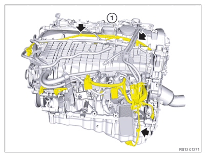
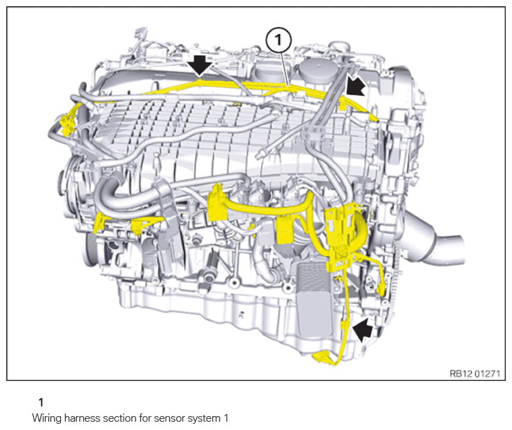
Wiring harness section for sensor system 1
NOTE:
RISK OF DAMAGE
Damage to wires when disconnecting connectors and plug connections.
Sheared wires can cause a short circuit.
Damage to wires when disconnecting connectors and plug connections.
Sheared wires can cause a short circuit.
- Do not pull on wires when disconnecting connectors and plug connections.
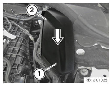
- Unlock and loosen clamp (1).
- Guide and remove cover (2) in arrow direction.
- Unlock and release the connector of the DME control unit.
- Unlock and release the connector of the integrated power supply module (PDM).
- Unlock and loosen the connector of the boost pressure sensor.
- Unlock and loosen the connector of the charge-air temperature sensor.
- Unlock and detach the connector of the crankshaft sensor.
- Unlock and detach the connector of the oil pressure switch.
- Unlock and loosen the connector of the solenoid valve.
- Unlock and loosen the connector of the heat management module.
- Unlock and detach the connector of the oil-level sensor.
- Unlock and loosen the connectors of the knock sensors.
- Unlock and detach the connector of the coolant temperature sensor.
- Unlock and detach the connector of the electric coolant pump.
- Unlock and detach the connector of the alternator.
- Unlock and detach the connector of the air conditioning compressor.
- Feed out the wiring harness section for sensor system 1 (1) and remove.