Installing the trailing arm
NOTE:
TECHNICAL INFORMATION
Tighten the screw connection in the normal position.
For additional information see: 33 00 Overview of TECHNICAL DATA
Tighten the screw connection in the normal position.
For additional information see: 33 00 Overview of TECHNICAL DATA
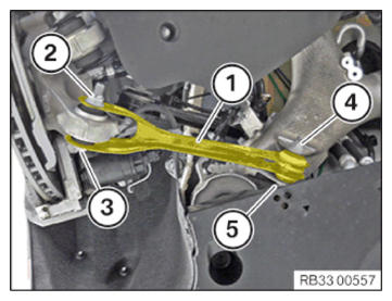
- Position the trailing arm (1).
- Replace all screws and nuts.
Parts: Bolts, nuts
- Insert screw (5) and mount nut (4).
- Insert screw (3) and mount nut (2).
- Tighten the nut (4) in NORMAL POSITION
.TIGHTENING TORQUES SPECIFICATION
Trailing arm to rear axle support M12
Replace screw and nut.Jointing torque 100 Nm Angle of rotation 90° - Tighten the nut (2) in NORMAL POSITION
.TIGHTENING TORQUES SPECIFICATION
Trailing arm to wheel carrier M12
Replace screw and nut.
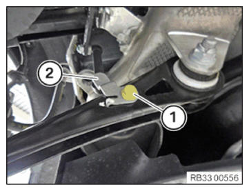
Tighten in normal position.Tightening torque 100 Nm Angle of rotation 90° - Position attachment rod (2) of ride height sensor on trailing arm.
- Tighten down screw (1).TIGHTENING TORQUES SPECIFICATION
Jointed rod ride height sensor on wishbone M6 Tightening torque 8 Nm
Follow-up Work
- Mount the WHEEL .
- Perform chassis ALIGNMENT CHECK .