Installing the camber control arm
NOTE:
TECHNICAL INFORMATION
The vehicle ride height may change as a result of turning the eccentric bolts for the adjustment of toe and camber. When replacing the bolts, make sure the eccentric bolts are correctly positioned to keep the ride height change to a minimum during the adjustment work.
The vehicle ride height may change as a result of turning the eccentric bolts for the adjustment of toe and camber. When replacing the bolts, make sure the eccentric bolts are correctly positioned to keep the ride height change to a minimum during the adjustment work.
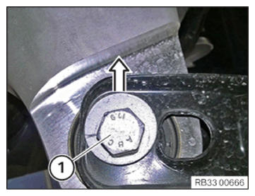
- Position the eccentric bolt (1) during replaceal in a way that the eccentric points vertically upwards!
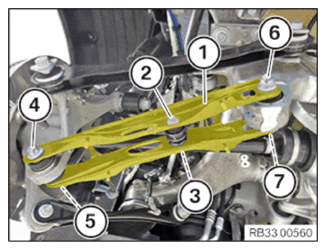
- Position the camber control arm (1).
- Replace the eccentric bolt (7), eccentric washer and the nut (6).
Parts: Eccentric bolt, eccentric washer, nut
- Insert eccentric bolt (7).
- Connect eccentric washer.
- Screw on the nut (6).
- Replace screw (4) and nut (5).
Parts: Bolt, nut
- Insert screw (4).
- Tighten nut (5).TIGHTENING TORQUES SPECIFICATION
Camber arm to wheel carrier M14
Replace screw and nut.Jointing torque 165 Nm Angle of rotation 90° - Replace screw (2) and nut (3).
Parts: Bolt, nut
- Insert screw (2).NOTE: TECHNICAL INFORMATION
Tighten the screw connection in the normal position.
For additional information see: 33 00 Overview of TECHNICAL DATA - Tighten the nut (3) in NORMAL POSITION
.TIGHTENING TORQUES SPECIFICATION
Anti-roll bar link to camber control arm M10
Replace screw and nut.
Tighten in normal position.Tightening torque 56 Nm Angle of rotation 90° - Tighten the nut (6) in NORMAL POSITION
.TIGHTENING TORQUES SPECIFICATION
Camber control arm to rear axle support M14
Replace bolt, nut and eccentric washer.
Tighten in normal position.Tightening torque 175 Nm
Follow-up Work
- Mount the WHEEL .
- Perform chassis ALIGNMENT CHECK .
- Install the camber control arm COVER .