Install the flexible disc for the rear propeller shaft
- Replace screws and self-locking nuts.
Parts: Self-locking nuts and bolts
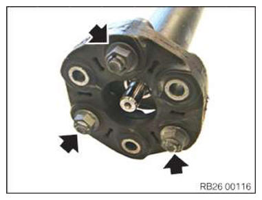
- Mount the flexible disc on the propeller shaft and tighten the bolts (arrows).TIGHTENING TORQUES SPECIFICATION
Flexible disc, rear, to prop shaft M12
Replace screws and nuts.
Joining torque and angle of rotation must be observed without fail.
Tightening via screw.
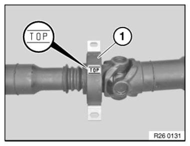
Joining torque 55 Nm Angle of rotation 90° - Central mount with the TOP designation:
Install the center mount (1) with the designation TOP at the top in the transmission tunnel.
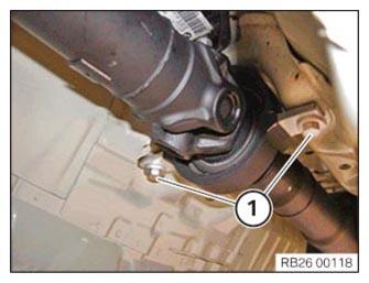
- Position central mount.
- Position screws (1).
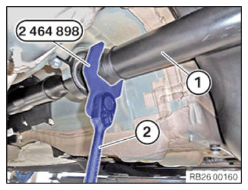
- Prop shafts with a narrow universal joint:
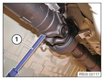
Use special tool 2 464 898 and a suitable tool (1) to protect the prop shaft (2) on the central universal joint from twisting.
- Prop shafts with a wide universal joint:
Secure the prop shaft with a suitable tool (1) against twisting at the middle universal joint.
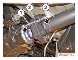
- Assemble the three-hole flange (1), flexible disc (2) and the propeller shaft (3) in the same position as marked during the disassembly.
- Replace screws.
Parts: Screws
- Tighten the screws.TIGHTENING TORQUES SPECIFICATION
Rear flexible disc to three-hole flange M12
Replace screws.
Joining torque and angle of rotation must be observed without fail.
Tightening via screw.
Joining torque 55 Nm Angle of rotation 90° - Tighten down screws (1).
TIGHTENING TORQUES SPECIFICATION
| Central mount to body | ||
|---|---|---|
| M8 | Tightening torque | 19 Nm |
Follow-up work
- Install the HEAT SHIELDS .
- If installed: install the right, and on the left TORSION STRUT where required.
- Install the CONNECTING SUPPORTS on the tunnel.
- Install the UNDERBODY PLANKING of the transmission on the side.
- Install rear UNDERBODY PROTECTION .