Remove the engine wiring harness for sensor system 1
WARNING:
Hot surfaces.
Risk of burning!
Risk of burning!
- Perform all work only on components that have cooled down.
Preliminary work
- Refer to BRINGING FRONT COMPARTMENT LID IN THE SERVICE POSITION .
- Refer to REMOVING THE COVER OF THE ENGINE COMPARTMENT AT THE REAR LEFT .
- Refer to REMOVING THE COVER OF THE REAR RIGHT ENGINE COMPARTMENT .
- Refer to DEACTIVATING THE 48 V ELECTRICAL SYSTEM .
- Refer to DISCONNECTING ALL BATTERY GROUND LEADS .
- Refer to REMOVING THE SEAL FOR THE HOOD REAR .
- Refer to REMOVING LEFT AND RIGHT WIPER ARM .
- Refer to REMOVING THE COWL COVER .
- Refer to REMOVING TRAILING LINK AT SPRING BOLT .
- Refer to REMOVING THE COWL UPPER PART IN THE CENTER .
- Refer to REMOVING THE CENTER BULKHEAD LOWER PART .
- Refer to REMOVING THE ACOUSTIC COVER .
- Refer to REMOVING ACOUSTIC COVER AT REAR .
- Refer to REMOVING THE DME CONTROL UNIT .
- Refer to REMOVING THE INTEGRATED SUPPLY MODULE (PDM) PARTIALLY .
- Refer to REMOVING THE CONTROL UNIT HOLDER .
- Refer to REMOVING THE COVER ON LEFT AND RIGHT IN THE ENGINE COMPARTMENT AT THE TOP .
- Refer to REMOVING BOTH FRONT-END STRUTS .
- Refer to REMOVING FRONT CROSS CONNECTION .
- Refer to REMOVING THE REAR TOP CROSS CONNECTION .
- Refer to REMOVING THE FAN COWL .
- Refer to REMOVING THE FRONT UNDERBODY PROTECTION OR FRONT THRUST FIELD .
- Refer to REMOVING THE UNDERBODY PROTECTION OF THE STEERING GEAR AND THRUST FIELD RESPECTIVELY .
- Refer to REMOVING THE CENTER UNDERBODY PROTECTION .
- Refer to REMOVING REAR UNDERBODY PROTECTION .
- Refer to DRAINING THE COOLANT FROM THE LOW-TEMPERATURE COOLING SYSTEM .
- Refer to CONNECTING THE COOLANT LINES FOR THE LOW-TEMPERATURE COOLANT CIRCUIT .
- Refer to REMOVING TANK VENT VALVE .
- Refer to REMOVING THE INTAKE PLENUM .
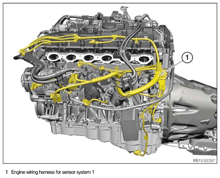
Engine wiring harness for sensor system 1
NOTE:
RISK OF DAMAGE
Electrostatic discharge.
Damage to or destruction of electrical components.
Electrostatic discharge.
Damage to or destruction of electrical components.
- Leave the electrical components in their original packaging until they are being installed. Only use the original packaging for returning the product. Always package removed components straight away.
- Read and comply with user information on using the associated special tool 12 7 060.
- Only tap the housings of electrical components. Do not tap pins or multi-pin connectors directly.
- Wear electrically conductive clothing and antistatic shoes (with ESD symbol).
- For additional information see: NOTES ON ESD (ELECTROSTATIC DISCHARGE) PROTECTION .
NOTE:
RISK OF DAMAGE
Damage to wires when disconnecting connectors and plug connections.
Sheared wires can cause a short circuit.
Damage to wires when disconnecting connectors and plug connections.
Sheared wires can cause a short circuit.
- Do not pull on wires when disconnecting connectors and plug connections.
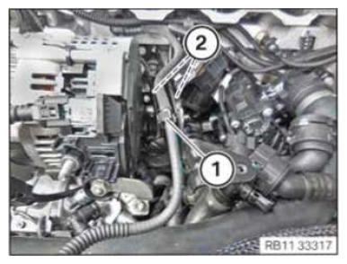
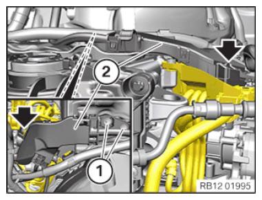
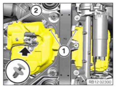
- Loosen clamp (1).
- Loosen clamps (2).
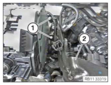
- Release the screws (1).
- Feed out the support (2) for the intake plenum and remove it.
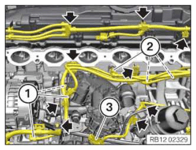
- Unlock and disconnect plug connections (1).
- Unlock plug connection (2) and disconnect.
- Unlock plug connection (3) and disconnect.
- Release the clamps (arrows).
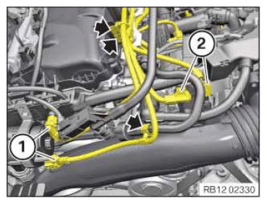
- Unlock and disconnect the plug connections (1) and (2).
- Release the clamps (arrows).
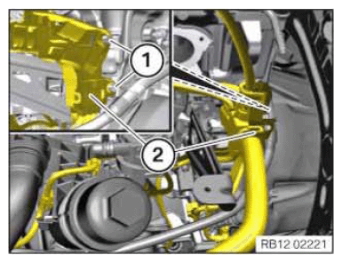
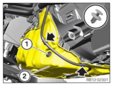
- Loosen screws (1).
- Unlock the lock (arrow).
- Remove the wiring harness section (2) and put to one side.
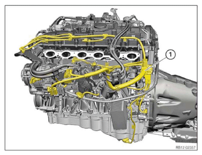
- Loosen screws (1).
- Feed out engine wiring harness (2) of sensor system 1 and set aside.
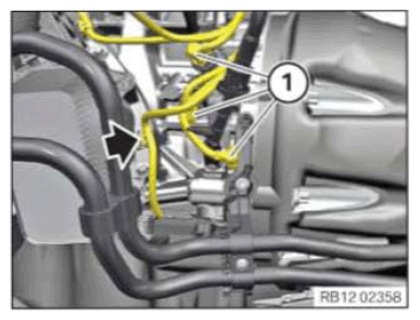
- Unlock and disconnect plug connections (1).
- Loosen the clamp (arrow).
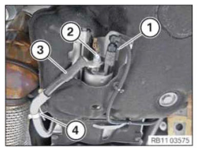
- Unlock plug connection (1) and disconnect.
- Loosen nuts (2).
- Release the positive battery cable (3) from the holder (4).
- Loosen the expanding rivet (1).
- Undo fir tree clip (2).
- Loosen the clamp (arrow).
- Loosen expending rivet (1).
- Release the clamps (arrows).
- Lower the acoustic cover (2).
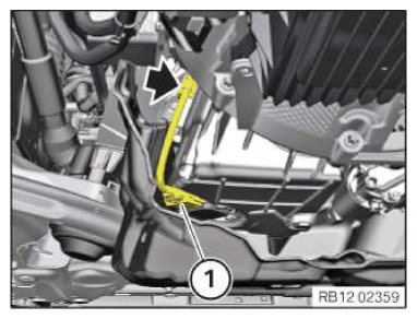
- Unlock dug connection (1) and disconnect.
- Loosen the lamp (arrow).
- Feed out engine wiring harness (1) for sensor system 1 and remove it.