Install the wiring harness section of the transmission wiring harness
Installing the wiring harness section for the right transmission wiring harness
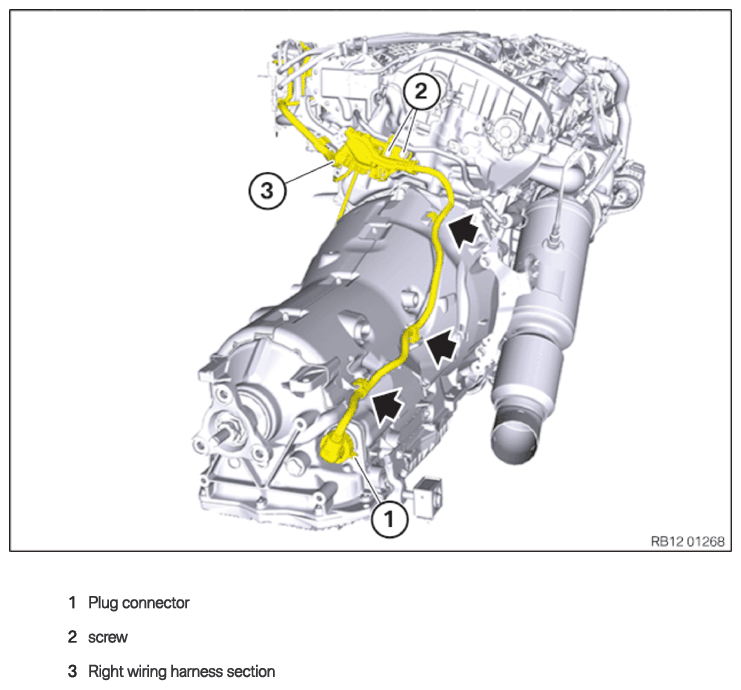
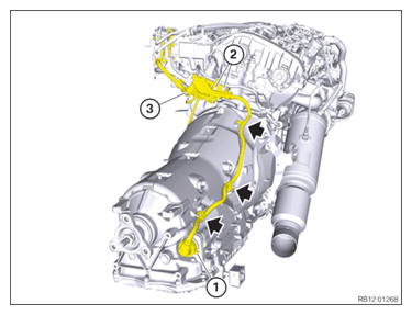
Wiring harness section of the transmission wiring harness, right
NOTE:
RISK OF DAMAGE
Improper routing of cables and wiring harnesses.
Trapped, crushed or damaged cables may cause short circuits and malfunctions.
Improper routing of cables and wiring harnesses.
Trapped, crushed or damaged cables may cause short circuits and malfunctions.
- Route all cables without abrasions, do not trap and crush.
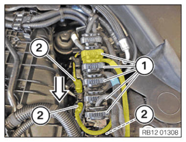
- Feed in and install the wiring harness section of the transmission wiring harness (3).
- Tighten down screws (2).TIGHTENING TORQUES SPECIFICATION
Wiring harness section for transmission to cylinder head M6x16 Tightening torque 8 Nm - Secure the clamps (arrows).
- Connect and lock the connector (1).
The connector must engage audibly.
Installing the wiring harness section of the transmission wiring harness on the left
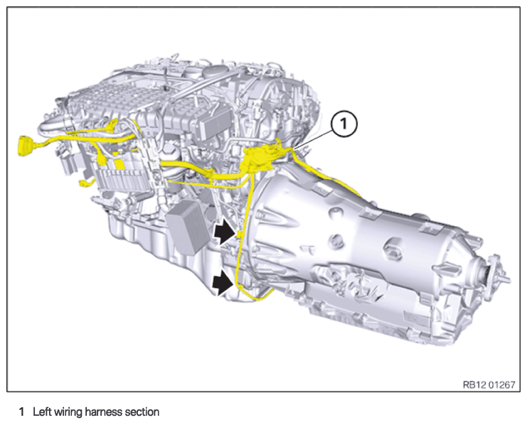
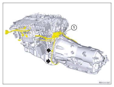
Wiring harness section of the transmission wiring harness, left
NOTE:
RISK OF DAMAGE
Improper routing of cables and wiring harnesses.
Trapped, crushed or damaged cables may cause short circuits and malfunctions.
Improper routing of cables and wiring harnesses.
Trapped, crushed or damaged cables may cause short circuits and malfunctions.
- Route all cables without abrasions, do not trap and crush.
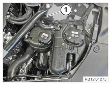
- Guide in the wiring harness section of the transmission wiring harness (1) and install.
- Secure the clamps (arrows).
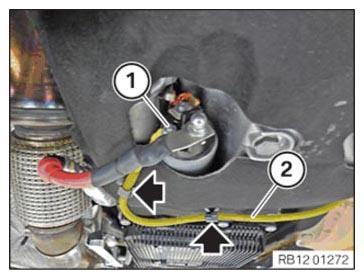
- Insert and install terminal 50 (2).
- Tighten nut (1).TIGHTENING TORQUES SPECIFICATION
Terminal 50 to starter motor M6 hexagon nut Tightening torque 7 Nm - Secure the clamps (arrows).
- Connect connector (1) in the direction of the arrow and lock.
All connectors (1) must engage audibly.
- Connect and lock the connector (1).
The connector (1) must engage audibly.
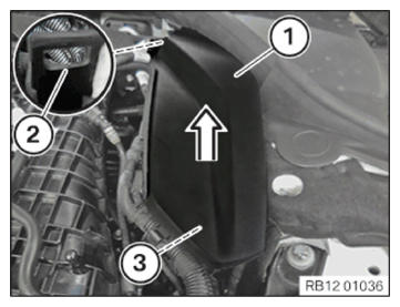
- Slide the cover (1) in the direction of the arrow into the guide (2) and install it.
- Lock clamp (3).
The clamp (3) must engage audibly.
Follow-up work
- Refer to FASTENING THE PROP SHAFT (PARTIALLY REMOVED) .
- Refer to INSTALLING TRANSMISSION CROSS MEMBER .
- Refer to INSTALLING THE HEAT SHIELDS .
- Refer to INSTALLING THE COMPLETE EXHAUST SYSTEM .
- Refer to INSTALLING THE CONNECTING SUPPORTS ON THE TUNNEL .
- Refer to INSTALLING THE THRUST FIELD .
- Refer to INSTALLING THE UNDERBODY PROTECTION OF THE STEERING GEAR OR THE FRONT THRUST FIELD .
- Refer to INSTALLING THE FRONT UNDERBODY PROTECTION OR FRONT THRUST FIELD .
- Refer to INSTALLING REAR UNDERBODY PROTECTION .
- Refer to INSTALLING THE UNDERBODY PLANKING OF THE TRANSMISSION ON THE SIDE .
- Refer to INSTALLING ACOUSTIC COVER AT REAR .
- Refer to INSTALLING THE CENTER COWL UPPER PART .
- Refer to INSTALLING TENSION STRUT ON SHOCK TOWER .
- Refer to INSTALLING WINDSHIELD PANEL COVER .
- Refer to INSTALLING LEFT AND RIGHT WIPER ARM .
- Refer to INSTALLING THE COVER OF THE ENGINE COMPARTMENT ON THE REAR LEFT .
- Refer to INSTALLING THE REAR RIGHT ENGINE COMPARTMENT COVER .
- Refer to INSTALLING ACOUSTIC COVER .
- Refer to INSTALLING THE FRONT HOOD SEAL AT THE REAR .
- Refer to CONNECTING NEGATIVE BATTERY CABLE .