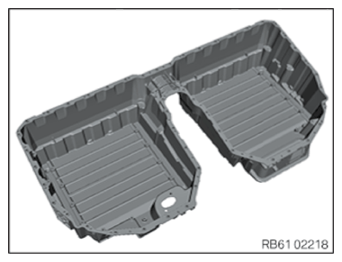
Replace the housing pan for the high-voltage battery unit
Check the lower housing section contamination and foreign bodies
WARNING:
High-voltage system.
The high-voltage system operates on the basis of hazardous, electrical voltage and high currents. Mortal hazard through electric shock!
The high-voltage system operates on the basis of hazardous, electrical voltage and high currents. Mortal hazard through electric shock!
- All work on the high-voltage system may only be carried out by specially trained and technically experienced personnel.
- For additional Information see: 61 00... SAFETY INSTRUCTIONS on handling hybrid cars
- For additional Information see: 61 25... Notes on REPAIR of high-voltage battery unit
Preliminary work
- POSITION PLAN
- Prepare the POSITION PLAN
- Remove the HOLDER
- Remove high-voltage battery unit LID .
- Remove the SAFETY BOX with holder
- Remove the battery management ELECTRONICS (SME) including holder.
- Remove the DISTRIBUTOR BLOCK .
- Remove CELL MODULE 3 .
- Remove the top RADIATOR .
- Remove the top removable PANEL .
- Remove CELL MODULE 4 .
- Remove the top removable PANEL .
- Remove communication WIRING HARNESS .
- Remove CELL MODULE 1 .
- Remove CELL MODULE 2 .
- Remove bottom RADIATOR .
- Remove CELL MODULE 5 .
- Remove CELL MODULE 6 .
- Remove DEGASSING UNIT .
- Remove high-voltage CONNECT LINE .
- Remove high-voltage CONNECTION .
- Remove high-voltage cables HOLDER .
Check
NOTE:
TECHNICAL INFORMATION
If the lid or lower housing section is replaced, a new nameplate must be ordered via the BMW Group parts sales.
If the lid or lower housing section is replaced, a new nameplate must be ordered via the BMW Group parts sales.
- Check the lower housing section contamination and foreign bodies.
Result
» The lower housing section is dirty or there are foreign bodies in the lower housing section.
Measure
- Clean with approved cleaning agent/remove foreign bodies.
Follow-up work
- Install VENTING UNIT .
- Install the for the high-voltage cables HOLDERS .
- Install high-voltage CONNECTION .
- Install high-voltage connect LINE .
- Install bottom RADIATOR .
- Install CELL MODULE 1 .
- Install CELL MODULE 2 .
- Install CELL MODULE 6 .
- Install CELL MODULE 5 .
- Install communication WIRING HARNESS .
- Install the top removable PANEL .
- Install top RADIATOR .
- Install CELL MODULE 3 .
- Tighten RADIATOR .
- Install CELL MODULE 4 .
- Install the DISTRIBUTOR BLOCK .
- Install the battery management ELECTRONICS (SME) including holder.
- Install the SAFETY BOX including holder.
- Install the high-voltage battery unit LID .
- Install the HOLDER .
- Perform EOS TEST