Installing exhaust turbocharger
NOTE:
RISK OF DAMAGE
Damage of the electric wastegate valve controller.
Excessive force when removing and installing a jammed exhaust turbocharger may damage the electric wastegate valve controller.
Damage of the electric wastegate valve controller.
Excessive force when removing and installing a jammed exhaust turbocharger may damage the electric wastegate valve controller.
- Do not pull on the electric wastegate valve controller.
- Apply force only at the turbine housing and exhaust manifold.
- Do not pull on the compressor housing.
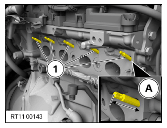
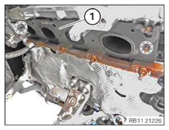
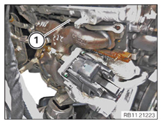
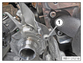
- Check the stud bolt (1) for damage, replace the stud bolt (1) if necessary.
Parts : Stud bolts
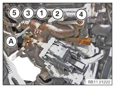
- Check the screw-in depth (A) of the upper stud bolt (1), screw in further if necessary.
TECHNICAL DATA - SCREW-IN DEPTH OF UPPER STUD BOLTS SPECIFICATION
| Screw-in depth of upper stud bolts on cylinder head | |
| Dimension A | 30 mm |
NOTE:
RISK OF DAMAGE
Damage to the surface.
The use of metal-cutting tools (e.g., emery cloths) for cleaning surfaces can damage them and lead to leaks and/or engine damage.
Damage to the surface.
The use of metal-cutting tools (e.g., emery cloths) for cleaning surfaces can damage them and lead to leaks and/or engine damage.
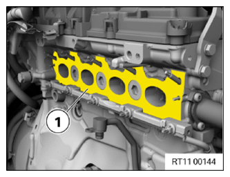
- Do not use any metal-cutting tools.
- Clean the sealing surfaces on the cylinder head (1) using special tool 0 495 102 (11 4 470) .
NOTE:
RISK OF DAMAGE
Damage to the surface.
The use of metal-cutting tools (e.g., emery cloths) for cleaning surfaces can damage them and lead to leaks and/or engine damage.
Damage to the surface.
The use of metal-cutting tools (e.g., emery cloths) for cleaning surfaces can damage them and lead to leaks and/or engine damage.
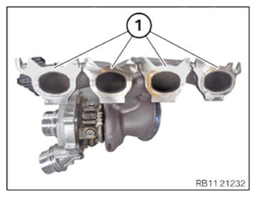
- Do not use any metal-cutting tools.
- Clean the sealing surfaces on the exhaust turbocharger (1) using special tool 0 495 102 (11 4 470)
.
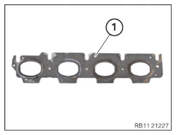
- Replace the seal (1).
Parts : Seals
- Guide in and install the seal (1).
- Make sure the seal (1) is correctly
installed in the guide pin in the marked
area.
- Replace the O-ring (1) on the oil feed line (2) for the exhaust turbocharger with the special tool 0 496 714 (00 9 030)
.
Parts : O-ring
NOTE:
TECHNICAL INFORMATION
A Observe the sign in the engine compartment! Only fill with approved engine oil of the correct (Society of Automotive Engineers) vise grade.
A Observe the sign in the engine compartment! Only fill with approved engine oil of the correct (Society of Automotive Engineers) vise grade.
- Fill the oil feed line (2) for the exhaust turbocharger up to the edge with motor oil.
Engine oil
Technically suitable engine oils for BMW Group engines
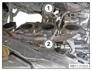
- Insert the exhaust turbocharger (2) and position it.
- Insert and position the oil feed line (1) for the exhaust turbocharger on the exhaust turbocharger (2).
CAUTION:
Heavy component.
Heavy components can lead to injury or damage.
Heavy components can lead to injury or damage.
- Remove and install heavy components with the aid of another person/other persons.
- Insert and install the exhaust turbocharger (1).
NOTE:
TECHNICAL INFORMATION
Note the installation position of the component. The component can be installed in various installation positions.
Note the installation position of the component. The component can be installed in various installation positions.
- Mount the sliding bar (1).
- The original BMW part number of the sliding bar (1) must be legible from the rear.
NOTE:
TECHNICAL INFORMATION
When assembling, it is essential to observe screwing sequences and tightening torques.
Failure to comply with the regulations can lead to leaks and damage.
When assembling, it is essential to observe screwing sequences and tightening torques.
Failure to comply with the regulations can lead to leaks and damage.
- Replace nuts (1) to (5).
Parts : Nuts
- Tighten the nuts in sequence (1) to (5).
TIGHTENING TORQUES SPECIFICATION
| Exhaust turbocharger to cylinder head | ||
| M7 Observe tightening sequence! Replace nuts. |
1. Joining torque | 10 Nm |
| 2. tightening torque | 10 Nm | |
| 3. Joining torque | 16 Nm | |
| 4. tightening torque | 16 Nm | |
| 5. Tightening torque | 16 Nm | |
Perform initial filling with the additive when replacing the exhaust turbocharger
NOTE:
RISK OF DAMAGE
Dry running due to insufficient initial filling of the exhaust turbocharger.
Damage to the exhaust turbocharger.
Dry running due to insufficient initial filling of the exhaust turbocharger.
Damage to the exhaust turbocharger.
- Be sure to do the initial filling when replacing the exhaust turbocharger.
- Fill the exhaust turbocharger with the matching additive (see applicable BMW parts catalogue).
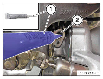
- Fill additive (1) in the bore (2) of the oil feed line.
CONSUMABLE - EXHAUST TURBOCHARGER ADDITIVE DESCRIPTION
| Exhaust turbocharger additive, gasoline MSP | 17 ml, Tube | 83192457276 |
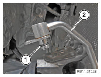
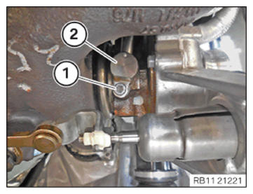
- Insert and install the oil feed line (2) for the exhaust turbocharger.
- Tighten down screw (1).
TIGHTENING TORQUES SPECIFICATION
| Oil feed line to exhaust turbocharger/crankcase | ||
| M6x12 | Tightening torque | 8 Nm |
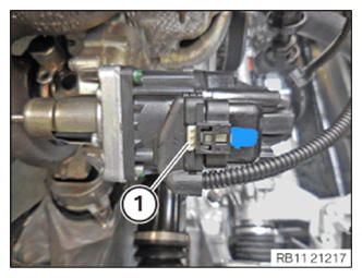
- Connect and lock the connector (1).
- Make sure the connector (1) engages audibly.
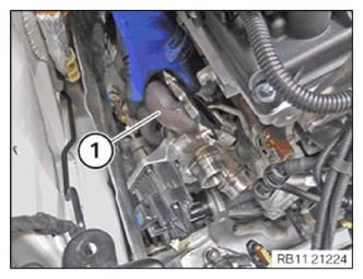
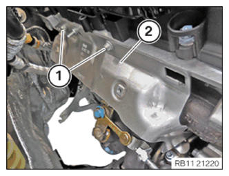
- Feed in and install the heat shield (2).
- Tighten down screws (1).
TIGHTENING TORQUES SPECIFICATION
| Heat shield to cylinder head | ||
| M8 x 12 | Tightening torque | 19 Nm |
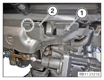
- Feed the heat shield (2) into the marked area and install it.
- Tighten down screw (1).
TIGHTENING TORQUES SPECIFICATION
| Heat shield to cylinder head | ||
| M8 x 12 | Tightening torque | 19 Nm |
- Tighten down screw (1).
TIGHTENING TORQUES SPECIFICATION
| Heat shield to trim strip | ||
| M6 x 12 | Tightening torque | 8 Nm |
Follow-up Work
- Refer to INSTALLING THE OIL RETURNING LINE FOR THE EXHAUST TURBOCHARGER .
- Refer to INSTALLING THE COOLANT RETURNING LINE FOR THE EXHAUST TURBOCHARGER .
- Refer to INSTALLING COOLANT LINE BETWEEN THE COOLANT PUMP AND CYLINDER HEAD .
- Refer to INSTALLING CATALYTIC CONVERTER .
- Refer to INSTALLING THE COMPLETE EXHAUST SYSTEM .
- Refer to INSTALLING THE CONNECTING SUPPORTS ON THE TUNNEL .
- Refer to INSTALLING FRONT OXYGEN SENSOR .
- Refer to INSTALLING THE ACOUSTIC COVER FOR THE ENGINE AT THE FRONT .
- Refer to INSTALLING CHARGE AIR LINE .
- Refer to INSTALLING CLEAN AIR PIPE .
- Refer to INSTALLING RESONATOR .
- Refer to INSTALLING ACOUSTIC COVER AT REAR .
- Refer to INSTALLING THE SEAL FOR THE BONNET .
- Refer to FILLING THE HIGH-TEMPERATURE COOLING SYSTEM WITH THE VACUUM FILLER DEVICE .
- Refer to BLEEDING THE HIGH-TEMPERATURE COOLANT CIRCUIT .
- Refer to CHECKING THE HIGH-TEMPERATURE COOLING SYSTEM FOR WATERTIGHTNESS .
- Refer to INSTALLING ACOUSTIC COVER .
- Refer to INSTALLING THE STIFFENING PLATE .
- Refer to INSTALLING THE UNDERBODY PROTECTION OF THE STEERING GEAR OR THE FRONT STIFFENING PLATE .
- Refer to CHECKING ENGINE OIL LEVEL .
- Refer to TAKING BONNET OUT OF THE SERVICE POSITION .