Install heat management module
NOTE:
TECHNICAL INFORMATION
The sealing surfaces must be free of oil, grease and cleaning agents.
The sealing surfaces must be free of oil, grease and cleaning agents.
NOTE:
RISK OF DAMAGE
Damage to the surface.
The use of metal-cutting tools (e.g., emery cloths) for cleaning surfaces can damage them and lead to leaks and/or engine damage.
Damage to the surface.
The use of metal-cutting tools (e.g., emery cloths) for cleaning surfaces can damage them and lead to leaks and/or engine damage.
- Do not use any metal-cutting tools.
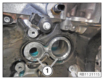
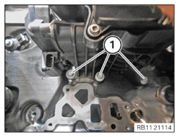
- Clean the sealing surfaces (1) on the crankcase with the special tool 0 495 102 (11 4 470).
- Replace the sealing rings (1)
.
Parts: Sealing rings
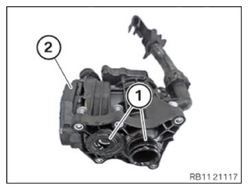
- Feed in the sealing rings (1)
at the heat management module (2)
and install.
- Correctly position the heat management module.
- Hand-tighten the bolts (1)
.
- Tighten down screws (2) .
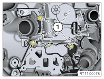
TIGHTENING TORQUES SPECIFICATION
| Heat exchange module to crankcase | ||
|---|---|---|
| M6 | tightening torque | 9 Nm |
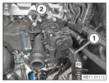
- Connect and lock the connector (1) .
- Make sure the connector (1) engages audibly.
- Tighten down screws (1) .
TIGHTENING TORQUES SPECIFICATION
| Heat exchange module to crankcase | ||
|---|---|---|
| M6 | tightening torque | 9 Nm |
NOTE:
RISK OF DAMAGE
Improper routing of cables and wiring harnesses.
Trapped, crushed or damaged cables may cause short circuits and malfunctions.
Improper routing of cables and wiring harnesses.
Trapped, crushed or damaged cables may cause short circuits and malfunctions.
- Route all cables without abrasions, do not trap and crush.
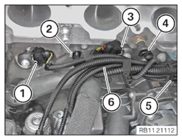
- Insert and position wiring harness section (6) for sensor system 1.
- Secure clamps (5) .
- Connect connectors (1) to (4) and lock.
- Make sure the connectors (1)
to (4)
engage audibly.
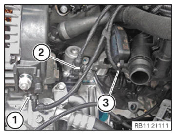
- Connect connectors (1) to (3) and lock.
- Make sure the connectors (1)
to (3)
engage audibly.
Follow-up work
- Refer to INSTALLING THE COMPLETE FULL-FLOW OIL FILTER .
- Refer to TIGHTENING THE OIL FILTER CAP .
- Refer to TOPPING UP THE MOTOR OIL .
- Refer to INSTALLING INTAKE PLENUM .
- Refer to INSTALLING THE TANK VENT VALVE .
- Refer to CONNECTING THE COOLANT LINES FOR THE HIGH-TEMPERATURE COOLANT CIRCUIT .
- Refer to CONNECTING THE COOLANT LINES FOR THE LOW-TEMPERATURE COOLANT CIRCUIT .
- Refer to INSTALLING THE ACOUSTIC COVER FOR THE ENGINE AT THE FRONT .
- Refer to INSTALLING CONTROL UNIT BRACKET .
- Refer to INSTALLING THE INTEGRATED POWER SUPPLY MODULE (PDM) .
- Refer to INSTALLING THE DME CONTROL UNIT .
- Refer to INSTALLING RESONATOR .
- Refer to FILLING THE LOW-TEMPERATURE COOLING SYSTEM WITH THE VACUUM FILLING EQUIPMENT
- Refer to FILLING THE HIGH-TEMPERATURE COOLING SYSTEM WITH THE VACUUM FILLING EQUIPMENT
- Refer to CONNECTING NEGATIVE BATTERY CABLE .
- Refer to VENTING THE HIGH-TEMPERATURE COOLANT SYSTEM .
- Refer to VENTING THE LOW-TEMPERATURE COOLING SYSTEM .
- Refer to CHECKING THE HIGH-TEMPERATURE COOLING SYSTEM FOR WATERTIGHTNESS .
- Refer to CHECKING LOW-TEMPERATURE COOLING SYSTEM FOR WATERTIGHTNESS .
- Refer to CHECKING ENGINE OIL LEVEL .
- Refer to INSTALLING THE FRONT UNDERBODY PROTECTION OR FRONT THRUST FIELD .
- Refer to INSTALLING THE UNDERBODY PROTECTION OF THE STEERING GEAR OR THE FRONT THRUST FIELD .
- Refer to INSTALLING THE CENTER UNDERBODY PROTECTION .
- Refer to INSTALLING REAR UNDERBODY PROTECTION .
- Refer to INSTALLING ACOUSTIC COVER AT REAR .
- Refer to INSTALLING ACOUSTIC COVER .
- Refer to INSTALLING THE FRONT HOOD SEAL AT THE REAR .
- Refer to TAKE HOOD OUT OF THE SERVICE POSITION .