Remove heat management module
WARNING:
Hot surfaces.
Risk of burning!
Risk of burning!
- Perform all work only on components that have cooled down.
WARNING:
Hot fluids.
Risk of scalding!
Risk of scalding!
- Conduct all work in the vehicle wearing appropriate personal protective equipment only.
NOTE:
TECHNICAL INFORMATION
Collect and dispose of emerging fluids. Observe country-specific waste disposal regulations.
Collect and dispose of emerging fluids. Observe country-specific waste disposal regulations.
Preliminary work
- Refer to DISCONNECTING ALL BATTERY GROUND LEADS .
- Refer to BRINGING FRONT COMPARTMENT LID IN THE SERVICE POSITION .
- Refer to REMOVING THE ACOUSTIC COVER .
- Refer to REMOVING THE SEAL FOR THE HOOD REAR .
- Refer to REMOVING ACOUSTIC COVER AT REAR .
- Refer to REMOVING THE COVER ON LEFT AND RIGHT IN THE ENGINE COMPARTMENT AT THE TOP .
- Refer to REMOVING BOTH FRONT-END STRUTS .
- Refer to REMOVING FRONT CROSS CONNECTION .
- Refer to REMOVING THE REAR TOP CROSS CONNECTION .
- Refer to REMOVING THE FAN COWL .
- Refer to REMOVING THE INTAKE FILTER HOUSING (TENSION STRUT ON SHOCK TOWER REMOVED) .
- Refer to REMOVING THE RESONATOR WITH THE TOP CLEAN AIR PIPE .
- Refer to REMOVING THE DME CONTROL UNIT (540i 2017-2020) , or REMOVING THE DME CONTROL UNIT (540i 2021-2022, 540i xDrive 2021-2022) .
- Refer to REMOVING THE INTEGRATED POWER SUPPLY MODULE (PDM) (540i 2017-2020) , or REMOVING THE INTEGRATED POWER SUPPLY MODULE (PDM) (540i 2021-2022, 540i xDrive 2021-2022) .
- Refer to REMOVING CONTROL UNIT BRACKET (540i 2017-2020) , or REMOVING THE CONTROL UNIT HOLDER (540i 2021-2022, 540i xDrive 2021-2022) .
- Refer to REMOVING THE FRONT UNDERBODY PROTECTION OR FRONT THRUST FIELD .
- Refer to REMOVING THE UNDERBODY PROTECTION OF THE STEERING GEAR AND THRUST FIELD RESPECTIVELY .
- Refer to DRAINING THE COOLANT FROM THE HIGH-TEMPERATURE COOLING SYSTEM .
- Refer to DRAINING THE COOLANT FROM THE LOW-TEMPERATURE COOLING SYSTEM .
- Refer to CONNECTING THE COOLANT LINES FOR THE HIGH-TEMPERATURE COOLANT CIRCUIT .
- Refer to CONNECTING THE COOLANT LINES FOR THE LOW-TEMPERATURE COOLANT CIRCUIT .
- Refer to REMOVING TANK VENT VALVE .
- Refer to REMOVING THE INTAKE PLENUM .
Further information is available.
NOTE:
RISK OF DAMAGE
Electrostatic discharge.
Damage to or destruction of electrical components.
Electrostatic discharge.
Damage to or destruction of electrical components.
- Leave the electrical components in their original packaging until they are being installed. Only use the original packaging for returning the product. Always package removed components straight away.
- Read and comply with user information on using the associated special tool 12 7 060.
- Only tap the housings of electrical components. Do not tap pins or multi-pin connectors directly.
- Wear electrically conductive clothing and antistatic shoes (with ESD symbol).
- For additional information see: NOTES ON ESD (ELECTROSTATIC DISCHARGE) PROTECTION
NOTE:
RISK OF DAMAGE
Damage to wires when disconnecting connectors and plug connections.
Sheared wires can cause a short circuit.
Damage to wires when disconnecting connectors and plug connections.
Sheared wires can cause a short circuit.
- Do not pull on wires when disconnecting connectors and plug connections.
NOTE:
TECHNICAL INFORMATION
Collect and dispose of emerging fluids. Observe country-specific waste disposal regulations.
Collect and dispose of emerging fluids. Observe country-specific waste disposal regulations.
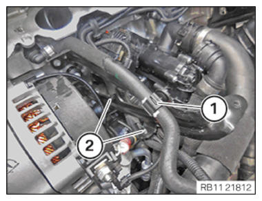
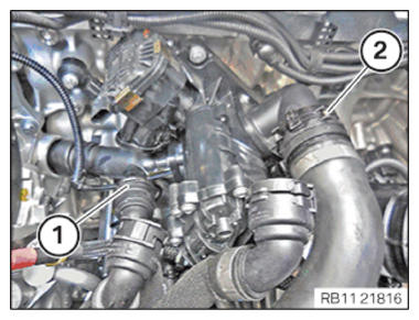
- Loosen clamp (1).
- Loosen clamps (2).
- Loosen screws (2).
- Feed out the support (2) for the intake plenum and remove it.
- Unlock and loosen coolant line (1).
- Catch and dispose of leakage coolant.
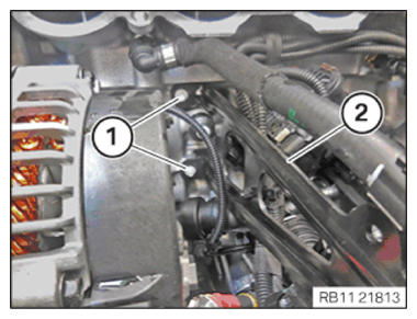
- Unlock and release the connector (1) for the alternator.
- Unlock and release the connector (2) for the knock sensor.
- Unlock and release the connector (3) for the heat management module.
- Unlock and loosen coolant line (1).
- Unlock and loosen coolant line (2).
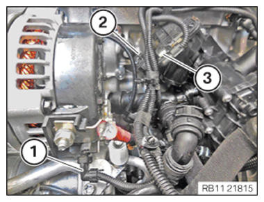
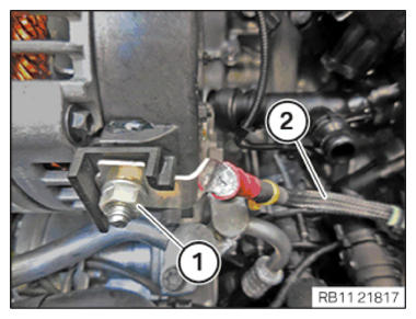
- Loosen nut (1).
- Thread out positive battery cable (2) and set it aside.
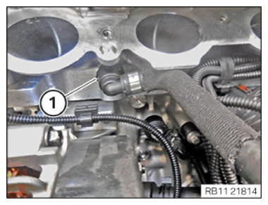
- Unlock and release the plug connection (1).
- Unlock and loosen coolant line (2).
- Catch and dispose of leakage coolant.
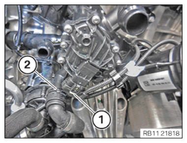
- Loosen clamps (1).
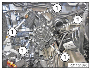
- Loosen screws (1).
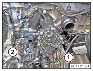
- Unlock and release the heat management module (1) together with the connecting pipe (2).
- Catch and dispose of leakage coolant.
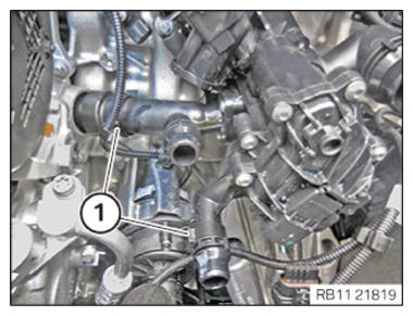
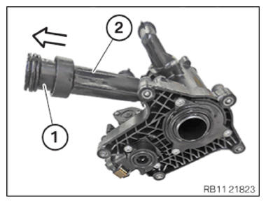
- Guide the connecting pipe (1) in the direction arrowed from the heat management module (2).