Install the coolant return line for the exhaust turbocharger
NOTE:
TECHNICAL INFORMATION
Make sure that the connections are locked correctly. The locks must engage audibly.
Make sure that the connections are locked correctly. The locks must engage audibly.
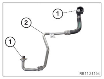
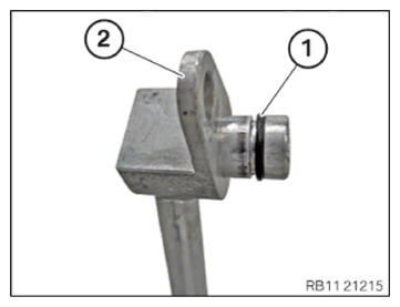
- Replace O-rings (1) on coolant return line (2) with special tool 0 496 714 (00 9 030).
Parts: O-rings
- Replace O-ring (1) on coolant feed line (2) with special tool 0 496 714 (00 9 030).
Parts: O-ring
- Insert and position the coolant return line (1) for the exhaust turbocharger.
- Connect the coolant return line (1) for the exhaust turbocharger and lock.
- Make sure that the coolant return line (1) for the exhaust turbocharger engages audibly.
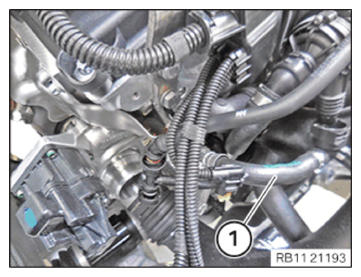
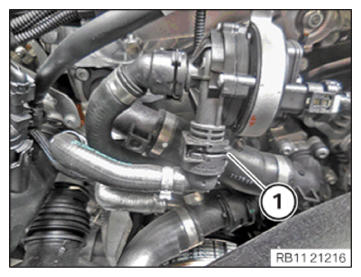
- Insert and install the coolant return line (4) for the exhaust turbocharger.
- Insert and install the coolant feed line (2) for the exhaust turbocharger.
- Tighten down screw (1).
TIGHTENING TORQUES SPECIFICATION
| Coolant feed line/coolant return line to exhaust turbocharger | ||
|---|---|---|
| M6x 12 | Tightening torque | 8 Nm |
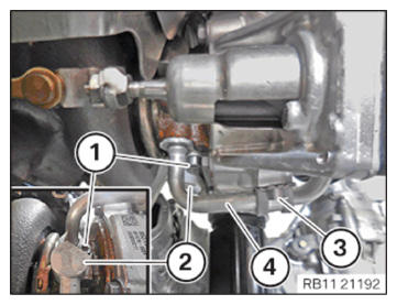
- Tighten down screw (3).
TIGHTENING TORQUES SPECIFICATION
| Coolant return line holder to exhaust turbocharger | ||
|---|---|---|
| M6 | Tightening torque | 8 Nm |
Follow-up work
- Refer to CONNECTING THE COOLANT LINES FOR THE HIGH-TEMPERATURE COOLANT CIRCUIT .
- Refer to INSTALLING THE ACOUSTIC COVER FOR THE ENGINE AT THE FRONT .
- Refer to INSTALLING CLEAN AIR PIPE .
- Refer to INSTALLING RESONATOR .
- Refer to INSTALLING ACOUSTIC COVER .
- Refer to FILLING THE HIGH-TEMPERATURE COOLING SYSTEM WITH THE VACUUM FILLING EQUIPMENT .
- Refer to VENTING THE HIGH-TEMPERATURE COOLANT SYSTEM .
- Refer to CHECKING THE HIGH-TEMPERATURE COOLING SYSTEM FOR WATERTIGHTNESS .
- Refer to INSTALLING THE CENTER UNDERBODY PROTECTION .
- Refer to INSTALLING THE UNDERBODY PROTECTION OF THE STEERING GEAR OR THE FRONT THRUST FIELD .