Installing the rail
NOTE:
TECHNICAL INFORMATION
When assembling, it is essential to observe screwing sequences and tightening torques.
Failure to comply with the regulations can lead to leaks and damage.
When assembling, it is essential to observe screwing sequences and tightening torques.
Failure to comply with the regulations can lead to leaks and damage.
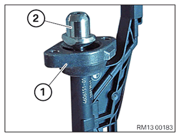
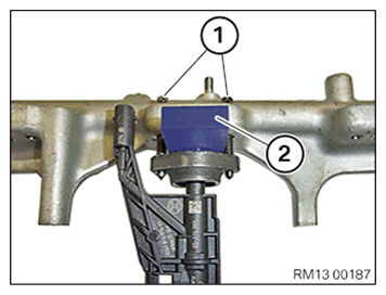
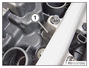
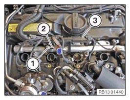
- Mount the holder (1) above the bayonet closure on (2) the injector.
- If the bracket (1) has a cast lug: Make sure that the holder is installed in the correct position.
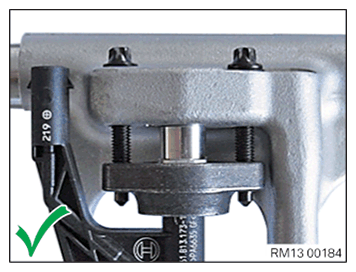
- If applicable, note the position of the cast lug:
The holder is mounted correctly when the cast lug is located at the rear.
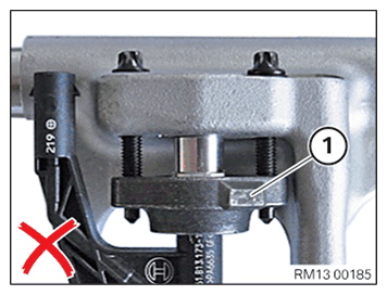
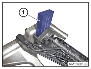
- If applicable, note the position of the cast lug:
The holder is mounted incorrectly when the cast lug (1) is in front.
NOTE:
RISK OF DAMAGE
Damage to injectors.
Weld seams on the injector may tear due to incorrect distances between the rail and injector so that the injector must be replaceed.
Damage to injectors.
Weld seams on the injector may tear due to incorrect distances between the rail and injector so that the injector must be replaceed.
- Insertion of the distance gauge is compulsory.
- Replace distance gauge, if a thickness of 8.5 mm is no longer given in the distance gauge.
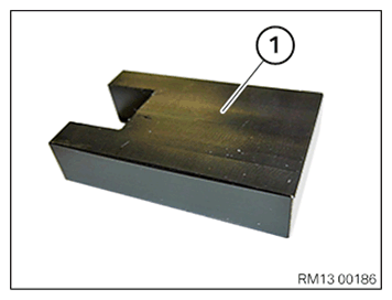
- Use the special tool (distance gouge) 2 358 022 (1).
- Mount the injectors with holders and the new bolts (M5x30) to the rail.
Parts: Screws (M5x30)
- Place the high-pressure rail on a clean table so that the openings on the high-pressure rail for the injectors point up.
The electrical injector connections must point to the fuel pressure sensor.
- Slide the special tool (distance gouge) 2 358 022 (2) between the holders and the rail onto the injector head.
- Make sure that the special tool (distance gauge) 2 358 022 (2) rests flat on the retaining bridge.
- Hand-tighten both screws (M5x30) (1) uniformly until special tool (distance gauge) 2 358 022 (2) rests flat against the rail and the holder.
- Remove the special tool (distance gouge) 2 358 022 (1).
- Repeat this operation for all injectors.
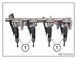
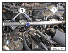
- Check the injectors (1) for a loose fit at the rail.
- Align the electrical injector connections parallel to the rail.
The injectors (1) must shift freely.
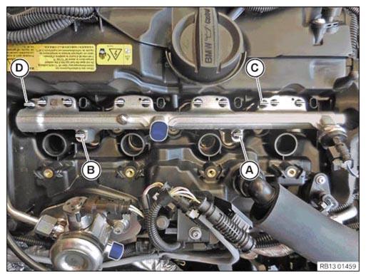
- Attach the rail (1) with the injectors to the cylinder head from the top.
- Make sure the injector tips catch the corresponding holes for the injectors in the cylinder head.
- Make sure the guides on the injector are properly inserted into the guide bore holes in the cylinder head.
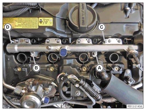
- Press down until resistance can be felt; position and hand-tighten the screws (M6x70) (A), (D), (B) and (C).
- Set the torque wrench to 2 Nm.
- Tighten the screws (A,) (D), (B) and (C) in alternating order by 90° each with the torque wrench until the rail is positioned flush on the cylinder head.
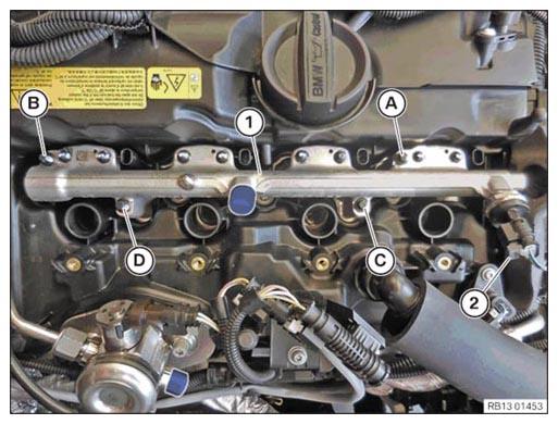
The figure shows the rail resting flat against the cylinder head.
- If the tightening torque (2 Nm) is reached before the rail rests on the cylinder head: Disassemble rail and start the installation procedure again.
NOTE:
TECHNICAL INFORMATION
When assembling, it is essential to observe screwing sequences and tightening torques.
Failure to comply with the regulations can lead to leaks and damage.
When assembling, it is essential to observe screwing sequences and tightening torques.
Failure to comply with the regulations can lead to leaks and damage.
- Tighten bolt (A) to 5 Nm.
- Tighten bolt (D) to 5 Nm.
- Tighten bolt (B) to 5 Nm.
- Tighten bolt (C) to 5 Nm.
- Connect connectors (2) and lock.
The connector (2) must engage audibly.
- Make sure that the rail (1) rests flat against the cylinder head.
- Attach a wrench socket set to an extension.
Do not use a reversible ratchet or torque wrench.
- Tighten the screws (M5x30) in pairs ((1) with (2), (3) with (4), (5) with (6), (7) with (8)) in alternating order to 90° hand-tight.
- Set the torque wrench to 5 Nm.
NOTE:
TECHNICAL INFORMATION
When assembling, it is essential to observe screwing sequences and tightening torques.
Failure to comply with the regulations can lead to leaks and damage.
When assembling, it is essential to observe screwing sequences and tightening torques.
Failure to comply with the regulations can lead to leaks and damage.
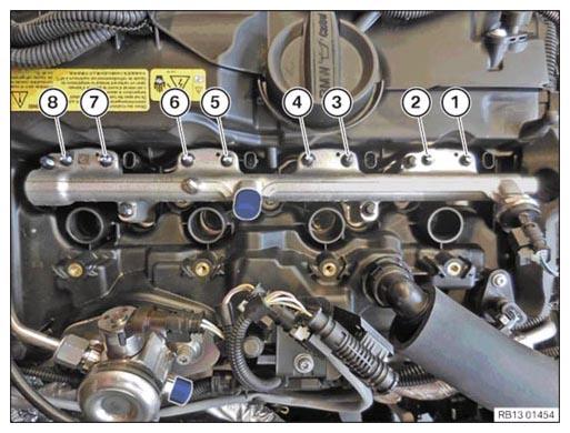
- Screw the M5x30 screws according to the following plan:
- Fuel injector 1:
- Tighten the bolt (1) at an angle of rotation of 90° with the torque wrench.
- Tighten the bolt (2) at an angle of rotation of 90° with the torque wrench.
- Repeat the operations for bolts (1) and (2) until both bolts reach a torque of 5 Nm.
- Fuel injector 2:
- Tighten the bolt (3) at an angle of rotation of 90° with the torque wrench.
- Tighten the bolt (4) at an angle of rotation of 90° with the torque wrench.
- Repeat the operations for bolts (3) and (4) until both bolts reach a torque of 5 Nm.
- Fuel injector 3:
- Tighten the bolt (5) at an angle of rotation of 90° with the torque wrench.
- Tighten the bolt (6) at an angle of rotation of 90° with the torque wrench.
- Repeat the operations for bolts (5) and (6) until both bolts have reached a torque of 5 Nm.
- Fuel injector 4:
- Tighten the bolt (7) at an angle of rotation of 90° with the torque wrench.
- Tighten the bolt (8) at an angle of rotation of 90° with the torque wrench.
- Repeat the operations for bolts (7) and (8) until both bolts reach a torque of 5 Nm.
- Mark all bolts (1) to (8) with a vertical line (see figure).
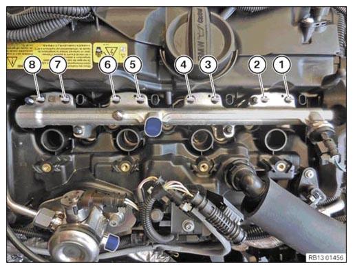
- Tighten screws using an angle of rotation.
- Tighten the bolt (1) with an angle of rotation of 90°.
- Tighten the bolt (2) with an angle of rotation of 90°.
- Tighten the bolt (3) with an angle of rotation of 90°.
- Tighten the bolt (4) with an angle of rotation of 90°.
- Tighten the bolt (5) with an angle of rotation of 90°.
- Tighten the bolt (6) with an angle of rotation of 90°.
- Tighten the bolt (7) with an angle of rotation of 90°.
- Tighten the bolt (8) with an angle of rotation of 90°.

- Check if all screws (1) to (8) have been tightened with a 90° angle of rotation.
Marks (lines) must be horizontal (see illustration).
- Release screws (M6x70) (A) to (D).
It is imperative that the bolts are unscrewed.
NOTE:
TECHNICAL INFORMATION
When assembling, it is essential to observe screwing sequences and tightening torques.
Failure to comply with the regulations can lead to leaks and damage.
When assembling, it is essential to observe screwing sequences and tightening torques.
Failure to comply with the regulations can lead to leaks and damage.

- Apply screw (A) with 5 Nm.
- Apply screw (D) with 5 Nm.
- Apply screw (B) with 5 Nm.
- Apply screw (C) with 5 Nm.
- Mark bolts (A) to (D) with a vertical line (see figure).
- Tighten screws (M6x70) (A) to (D) with an angle of rotation of 90°.
- Check if screws (A) to (D) were tightened with an angle of rotation of 90°
.
The marks (lines) must be horizontal (see figure).
- Connect all connectors (1) to the injectors and lock.
All connectors (1) must audibly engage.
- Thread in cable duct (3) and install.
- Thread in ground cable (2) and install.
- Tighten the nut (1).
TIGHTENING TORQUES SPECIFICATION
| Ground cable to rail | ||
| M6 | Tightening torque | 5 Nm |
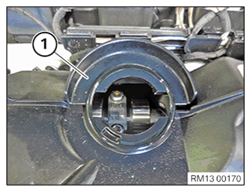
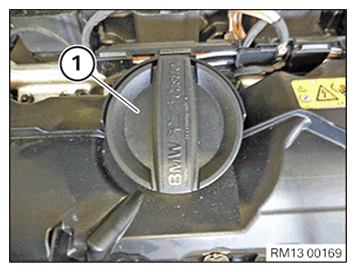
- Unscrew the sealing cap (1) from the oil filler neck.
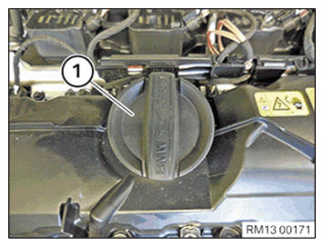
- Mount the drip shield (1) on the cylinder head cover.
- Screw the sealing cap (1) onto the oil filler neck.
Follow-up work
- Refer to INSTALLING THE HIGH-PRESSURE LINE BETWEEN THE HIGH-PRESSURE PUMP AND THE HIGH-PRESSURE RAIL .
- Refer to INSTALLING THE IGNITION COILS .
- Refer to DISCONNECTING ALL BATTERY GROUND LEADS .
- Refer to INSTALL THE CYLINDER HEAD COVER ACOUSTIC COVER
- Refer to INSTALLING ACOUSTIC COVER AT REAR .
- Refer to INSTALL ACOUSTIC COVER .
- Refer to INSTALL THE FRONT HOOD SEAL AT THE REAR .