Install the complete full-flow oil filter
Full-flow oil filter
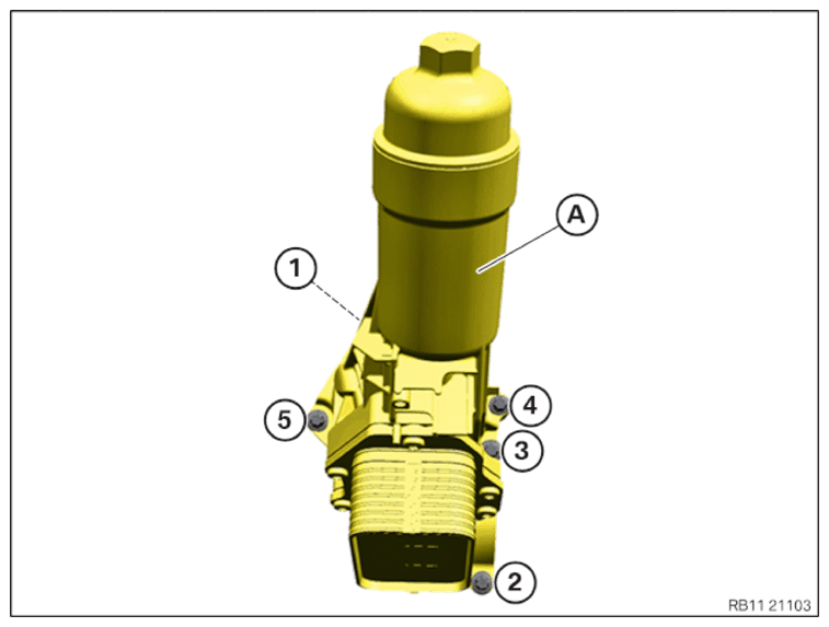
A Full-flow oil filter
1 - Screws
5
NOTE:
TECHNICAL INFORMATION
The sealing surfaces must be free of oil, grease and cleaning agents.
The sealing surfaces must be free of oil, grease and cleaning agents.
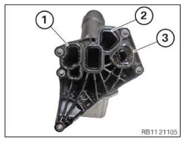
- Replace the gaskets (1), (2) and (3) on the full-flow oil filter.
Parts: Seals
NOTE:
RISK OF DAMAGE
Damage to the surface.
The use of metal-cutting tools (e.g., emery cloths) for cleaning surfaces can damage them and lead to leaks and/or engine damage.
Damage to the surface.
The use of metal-cutting tools (e.g., emery cloths) for cleaning surfaces can damage them and lead to leaks and/or engine damage.
- Do not use any metal-cutting tools.
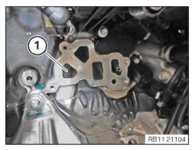
- Clean the sealing residue off the sealing surface (1) on the crankcase using the special tool 0 495 102 (11 4 470).
- Have a cleaning cloth ready.
NOTE:
RISK OF DAMAGE
Damage to the engine.
If the engine is manually rotated in the wrong direction of rotation, the engine can be damaged.
Damage to the engine.
If the engine is manually rotated in the wrong direction of rotation, the engine can be damaged.
- Only rotate the engine manually in the correct direction of rotation: a) clockwise when looking at the damper, or b) counterclockwise when looking at the chain drive. b) applies only if the timing chain is installed in the rear.
- Crank the engine with the special tool 0 493 380 (11 6 480) until the motor oil flows in the area of the oil duct (1).
- Install full-flow oil filter (2) from the top and position it.
- Hand-tighten the bolts (1).
- Apply the screws (1) the full-flow oil filter (2) hand tight.
- Apply the screws (1) the full-flow oil filter (2) hand tight.
NOTE:
TECHNICAL INFORMATION
When assembling, it is essential to observe screwing sequences and tightening torques.
Failure to comply with the regulations can lead to leaks and damage.
When assembling, it is essential to observe screwing sequences and tightening torques.
Failure to comply with the regulations can lead to leaks and damage.
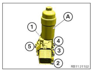
- Tighten the screw at the full-flow oil filter (A) in the order (1) to (5).
TIGHTENING TORQUES SPECIFICATION
| Full-flow oil filter to crankcase | ||
|---|---|---|
| M6 Observe tightening sequence. |
Joining torque | 4 Nm |
| Tightening torque | 10 Nm | |
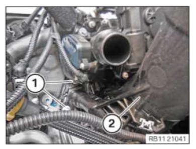
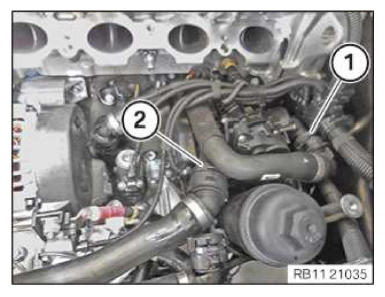
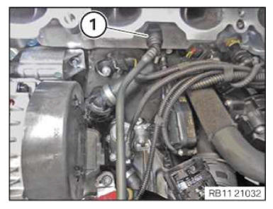
- Feed in and install the coolant line (1) on the full-flow oil filter (2).
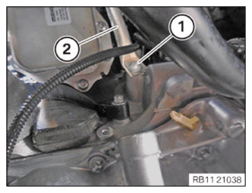
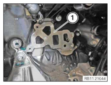
- Feed in and install the manifold bracket (2).
- Tighten down screw (1).
TIGHTENING TORQUES SPECIFICATION
| Test gauge to basic carrier | ||
|---|---|---|
| M6x16 | Tightening torque | 8 Nm |
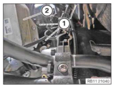
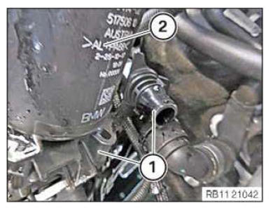
- Secure clamps (1).
- Connect and lock coolant line (2).
- Make sure that the cooling line (2) engages audibly.
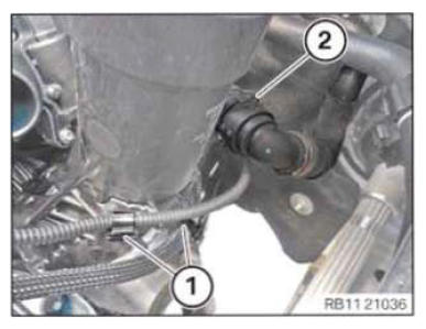
- Connect and lock coolant line (1).
- Connect and lock coolant line (2).
- Make sure that you can hear coolant lines (1) and (2) engage.
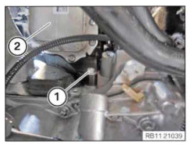
- Feed in and install coolant line (1).
- Make sure that the cooling line (1) engages audibly.
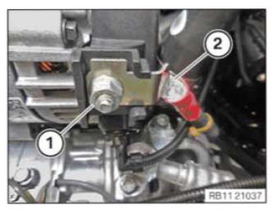
CAUTION:
Improper routing of the positive battery cable.
Risk of short circuits!
Risk of short circuits!
- Route the positive battery cable without abrasions and do not trap.
- Insert and install the positive battery cable (2).
- Tighten nut (1).TIGHTENING TORQUES SPECIFICATION
Positive battery cable to the alternator M6 Tightening torque 8 Nm
Follow-up work
- Refer to TIGHTENING THE OIL FILTER CAP .
- Refer to TOPPING UP THE MOTOR OIL .
- Refer to INSTALLING INTAKE PLENUM .
- Refer to INSTALLING THE TANK VENT VALVE .
- Refer to CONNECTING THE COOLANT LINES FOR THE HIGH-TEMPERATURE COOLANT CIRCUIT .
- Refer to CONNECTING THE COOLANT LINES FOR THE LOW-TEMPERATURE COOLANT CIRCUIT .
- Refer to INSTALLING THE ACOUSTIC COVER FOR THE ENGINE AT THE FRONT .
- Refer to INSTALLING CONTROL UNIT BRACKET .
- Refer to INSTALLING THE INTEGRATED POWER SUPPLY MODULE (PDM) .
- Refer to INSTALLING THE DME CONTROL UNIT .
- Refer to INSTALLING RESONATOR .
- Refer to FILLING THE LOW-TEMPERATURE COOLING SYSTEM WITH THE VACUUM FILLING EQUIPMENT .
- Refer to FILLING THE HIGH-TEMPERATURE COOLING SYSTEM WITH THE VACUUM FILLING EQUIPMENT .
- Refer to CONNECTING NEGATIVE BATTERY CABLE .
- Refer to VENTING THE HIGH-TEMPERATURE COOLANT SYSTEM .
- Refer to VENTING THE LOW-TEMPERATURE COOLING SYSTEM .
- Refer to CHECKING THE HIGH-TEMPERATURE COOLING SYSTEM FOR WATERTIGHTNESS .
- Refer to CHECKING LOW-TEMPERATURE COOLING SYSTEM FOR WATERTIGHTNESS .
- Refer to CHECKING ENGINE OIL LEVEL .
- Refer to INSTALLING THE FRONT UNDERBODY PROTECTION OR FRONT THRUST FIELD .
- Refer to INSTALLING THE UNDERBODY PROTECTION OF THE STEERING GEAR OR THE FRONT THRUST FIELD .
- Refer to INSTALLING THE CENTER UNDERBODY PROTECTION .
- Refer to INSTALLING REAR UNDERBODY PROTECTION .
- Refer to INSTALLING ACOUSTIC COVER AT REAR .
- Refer to INSTALLING ACOUSTIC COVER .
- Refer to INSTALLING THE FRONT HOOD SEAL AT THE REAR .
- Refer to TAKING HOOD OUT OF THE SERVICE POSITION .