Install full-flow oil filter
Full-flow oil filter
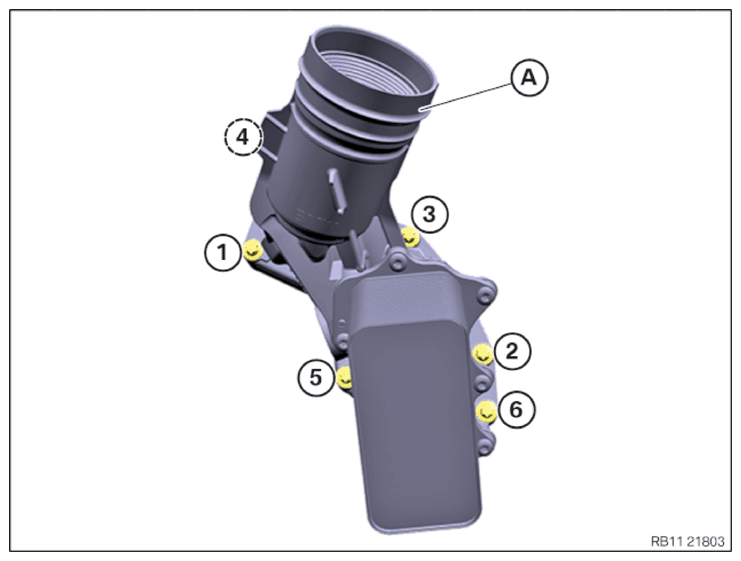
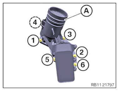
A Full-flow oil filter
1 - 6 Screws
NOTE:
TECHNICAL INFORMATION
Only G05 and G07
On vehicles with an active stabilizer (ARS), the fan cowl must be removed to crank the engine.
For additional information see: REMOVING AND INSTALLING/REPLACING FAN COWL WITH ELECTRIC FAN .
Only G05 and G07
On vehicles with an active stabilizer (ARS), the fan cowl must be removed to crank the engine.
For additional information see: REMOVING AND INSTALLING/REPLACING FAN COWL WITH ELECTRIC FAN .
NOTE:
TECHNICAL INFORMATION
The sealing surfaces must be free of oil, grease and cleaning agents.
The sealing surfaces must be free of oil, grease and cleaning agents.
- Have a cleaning cloth ready.NOTE: RISK OF DAMAGE
Damage to the engine.
If the engine is manually rotated in the wrong direction of rotation, the engine can be damaged.- Only rotate the engine manually in the correct direction of rotation: a) clockwise when looking at the damper, or b) counterclockwise when looking at the chain drive. b) applies only if the timing chain is installed in the rear.
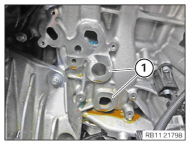
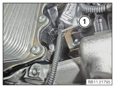
- Crank the engine with the special tool 0 493 380 (11 6 480) until the motor oil flows in the area of the oil duct (1).
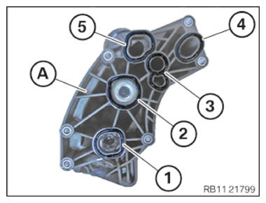
- Replace seals (1) to (5) on the full-flow oil filter (A).
Parts: Seals
NOTE: RISK OF DAMAGE
Damage to the surface.
The use of metal-cutting tools (e.g., emery cloths) for cleaning surfaces can damage them and lead to leaks and/or engine damage.- Do not use any metal-cutting tools.
- Clean the sealing residue off the sealing surface (1) on the crankcase using the special tool 0 495 102 (11 4 470)
.
- Feed in and install the full-flow oil filter (A) from above.
- Tighten screws in the order (1) to (6).NOTE: Tighten the bolts in 360 degree steps.TIGHTENING TORQUES SPECIFICATION
Full-flow oil filter to crankcase Captive screw M6
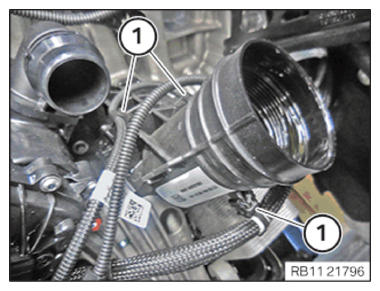
Observe tightening sequence!Joining torque 4 Nm tightening torque 10 Nm - Secure clamps (1).
- Secure clamps (1).NOTE: TECHNICAL INFORMATION
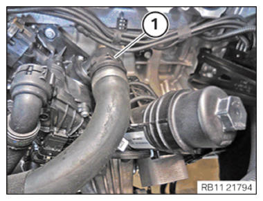
Make sure that the connections are locked correctly. The locks must engage audibly. - Connect coolant hose (1) and lock.
Follow-up work
- Refer to INSTALLING THE OIL FILTER ELEMENT (540I 2017-2020) , or INSTALLING THE OIL FILTER ELEMENT (540i 2021-2022) .
- Refer to INSTALLING THE INTAKE PLENUM .
- Refer to INSTALLING THE TANK VENT VALVE .
- Refer to INSTALLING CONTROL UNIT BRACKET (540i 2017-2020) , or CONNECTING THE COOLANT LINES FOR THE HIGH-TEMPERATURE COOLANT CIRCUIT .
- Refer to INSTALLING THE INTEGRATED POWER SUPPLY MODULE (PDM) (540i 2017-2020) , or INSTALLING THE INTEGRATED POWER SUPPLY MODULE (PDM) (540i 2021-2022) .
- Refer to INSTALLING THE DME CONTROL UNIT (540i 2017-2020) , or INSTALLING THE DME CONTROL UNIT (540i 2021-2022) .
- Refer to INSTALLING THE RESONATOR WITH THE TOP CLEAN AIR PIPE .
- Refer to INSTALLING INTAKE SILENCER HOUSING .
- Refer to INSTALLING FAN COWL .
- Refer to INSTALLING THE REAR TOP CROSS CONNECTION .
- Refer to INSTALLING FRONT CROSS CONNECTION .
- Refer to INSTALLING BOTH FRONT-END STRUTS .
- Refer to INSTALLING THE COVER ON THE LEFT AND RIGHT IN THE ENGINE COMPARTMENT AT THE TOP .
- Refer to FILLING ENGINE OIL .
- Refer to OPENING THE OIL FILLER CAP .
- Refer to FILLING THE HIGH-TEMPERATURE COOLING SYSTEM WITH THE VACUUM FILLING EQUIPMENT .
- Refer to FILLING THE LOW-TEMPERATURE COOLING SYSTEM WITH THE VACUUM FILLING EQUIPMENT .
- Refer to CONNECTING NEGATIVE BATTERY CABLE .
- Refer to VENTING THE HIGH-TEMPERATURE COOLANT SYSTEM .
- Refer to VENTING THE LOW-TEMPERATURE COOLING SYSTEM .
- Refer to CHECKING ENGINE OIL LEVEL .
- Refer to INSTALLING THE CENTER UNDERBODY PROTECTION .
- Refer to INSTALLING THE UNDERBODY PROTECTION OF THE STEERING GEAR OR THE FRONT THRUST FIELD .
- Refer to INSTALLING THE FRONT UNDERBODY PROTECTION OR FRONT THRUST FIELD .
- Refer to INSTALLING ACOUSTIC COVER AT REAR .
- Refer to INSTALLING THE FRONT HOOD SEAL AT THE REAR .
- Refer to INSTALLING ACOUSTIC COVER .
- Refer to TAKING HOOD OUT OF THE SERVICE POSITION .