Checking cylinder head for watertightness
CAUTION:
Spring preload.
Injury hazard!
Injury hazard!
- The use of the specified special tool (tool) is mandatory.
- Carry out the described steps properly.
NOTE:
RISK OF DAMAGE
Contaminant or foreign body.
Contamination can result in malfunctions, loss of function or leaks.
Contaminant or foreign body.
Contamination can result in malfunctions, loss of function or leaks.
- Adhere to the utmost cleanliness.
- Protect components from contamination e.g. by covering.
- Close off line connections with seal plugs.
Preliminary work
- Refer to REMOVING THE EXHAUST TURBOCHARGER (CYLINDER HEAD REMOVED) .
- Refer to INSTALLING THE CYLINDER HEAD ON THE ASSEMBLY JIG .
- Refer to ADJUSTING THE SERVOMOTOR TO MINIMUM LIFT .
- Refer to CHECKING THE POSITION OF THE INTAKE CAMSHAFT .
- Refer to REMOVE TORSION SPRINGS .
- Refer to REMOVING ALL GATES .
- Refer to REMOVING ALL INTERMEDIATE LEVERS .
- Refer to REMOVE INTAKE CAMSHAFT .
- Refer to REMOVE THE SERVOMOTOR FOR THE ECCENTRIC SHAFT (CYLINDER HEAD REMOVED) .
- Refer to REMOVE ECCENTRIC SHAFT .
- Refer to REMOVE EXHAUST CAMSHAFT .
- Refer to REMOVE ALL ROLLER CAM FOLLOWERS .
- Refer to REMOVING ALL HYDRAULIC VALVE CLEARANCE COMPENSATING ELEMENTS .
- Refer to REMOVE ALL VALVE SPRINGS .
- Refer to REMOVE VALVE STEM SEALS .
- Refer to REMOVE ALL VALVES .
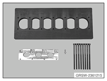
- Get the set of special tools 2 361 215
ready.
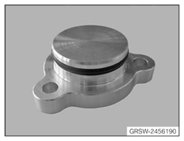
- Have the special tool 2 456 190
ready.
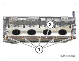
- Loosen nuts (1).
- Guide out and remove the trim strip (2).
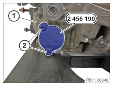
- Insert and install the special tool 2 456 190 at the cylinder head (2).
- Tighten down screws (2).TIGHTENING TORQUES SPECIFICATION
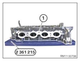
Special tool 2 456 190 to cylinder head M6X20 Tightening torque 8 Nm - Position the cylinder head (1) on the special tool 2 361 215 so that the rubber layer faces the cylinder r head (1) and all water ducts at the cylinder head (1) are closed.
- Mount the cylinder head (1).TIGHTENING TORQUES SPECIFICATION
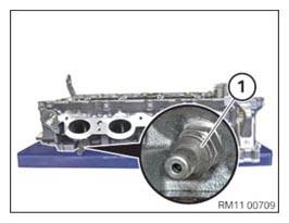
Cylinder head to special tool 2 361 215 Tightening torque 35 Nm - Disassemble the venting connector (1).
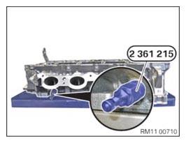
- Mount the valve of the special tool 2 361 215
on the cylinder head.TIGHTENING TORQUES SPECIFICATION
Venting connector/special tool to cylinder head M10 Tightening torque 18 Nm Check
- Heat up the cylinder head.TECHNICAL DATA - CYLINDER HEAD WATERTIGHTNESS SPECIFICATION
Check for cylinder head watertightness Temperature of the cylinder head 60°C - Connect compressed air.TECHNICAL DATA - CYLINDER HEAD WATERTIGHTNESS SPECIFICATION
Check for cylinder head watertightness Testing pressure max. 3.0 bar - Check the cylinder head in for tightness in a water bath.
Result
» Air bubbles develop.
Measure
- Check the cylinder head for damage at the point of exit of the air bubbles. If necessary, repair or replace the cylinder head.
- Disassemble the valve of the special tool 2 361 215.
- Mount the venting connector (1).TIGHTENING TORQUES SPECIFICATION
Venting connector/special tool to cylinder head M10 Tightening torque 18 Nm - Mount the trim strip (2).
- Tighten nuts (1).TIGHTENING TORQUES SPECIFICATION
Trim strip at the cylinder head M7 Tightening torque 18 Nm - Loosen screws (2).
- Guide out and remove the special tool 2 456 190
from the cylinder head (2).
Follow-up work
- Refer to INSTALL ALL VALVES .
- Refer to INSTALLING VALVE STEM SEALS .
- Refer to INSTALL ALL VALVE SPRINGS .
- Refer to INSTALLING ALL HYDRAULIC VALVE CLEARANCE COMPENSATING ELEMENTS .
- Refer to INSTALL ALL ROLLER CAM FOLLOWERS .
- Refer to INSTALL ECCENTRIC SHAFT .
- Refer to INSTALLING THE SERVOMOTOR FOR THE ECCENTRIC SHAFT (CYLINDER HEAD REMOVED) .
- Refer to INSTALL INTAKE CAMSHAFT .
- Refer to INSTALL EXHAUST CAMSHAFT .
- Refer to CHECKING THE INTERMEDIATE LEVER CLASSIFICATION .
- Refer to INSTALLING ALL INTERMEDIATE LEVERS .
- Refer to INSTALLING ALL GATES .
- Refer to INSTALLING TORSION SPRINGS .
- Refer to REMOVING THE CYLINDER HEAD FROM THE ASSEMBLY JIG .
- Refer to INSTALLING THE EXHAUST TURBOCHARGER (CYLINDER HEAD REMOVED) .