Removing all intermediate levers
NOTE:
DANGER
High-voltage system.
The high-voltage system operates on the basis of hazardous, electrical voltage and high currents. Mortal hazard through electric shock!
High-voltage system.
The high-voltage system operates on the basis of hazardous, electrical voltage and high currents. Mortal hazard through electric shock!
- All work on the high-voltage system may only be carried out by specially trained and technically experienced personnel.
- For additional information see:
- For additional information see:
WARNING:
Hot surfaces.
Risk of burning!
Risk of burning!
- Perform all work only on components that have cooled down.
WARNING:
Working on fuel system.
Risk of fire! Danger of explosion!
Risk of fire! Danger of explosion!
- When working on the fuel system, make sure the workstation has sufficient ventilation, e.g., by means of extraction.
- Tightly seal off open lines and connections; collect any leakage fuel directly at the point of exit.
- No fire, sparks, open flames or smoking.
CAUTION:
On releasing high pressure line, fuel may emerge at high speed.
Injury hazard!
Injury hazard!
- Wear suitable personal protective equipment.
- Before performing any Installation work, allow cooling system to cool down to less than 40°C.
- Note warnings on cylinder head cover.
NOTE:
TECHNICAL INFORMATION
Collect and dispose of emerging fluids. Observe country-specific waste disposal regulations.
Collect and dispose of emerging fluids. Observe country-specific waste disposal regulations.
Preliminary work
- Refer to BRINGING FRONT COMPARTMENT LID IN THE SERVICE POSITION .
- Refer to REMOVING THE ACOUSTIC COVER .
- Refer to REMOVING THE COVER OF THE ENGINE COMPARTMENT AT THE REAR LEFT .
- Refer to REMOVING THE SEAL FOR THE HOOD REAR .
- Refer to REMOVING LEFT AND RIGHT WIPER ARM .
- Refer to REMOVING THE COVER OF THE REAR RIGHT ENGINE COMPARTMENT .
- Refer to REMOVING TRAILING LINK AT SPRING BOLT .
- Refer to REMOVING THE CENTER COWL UPPER PART .
- Refer to REMOVING RIGHT SEALING FRAME .
- Refer to LOOSENING HIGH-VOLTAGE CABLES ON THE ELECTRICAL MACHINE ELECTRONICS .
- Refer to REMOVING ACOUSTIC COVER AT REAR .
- Refer to REMOVING LEFT SEALING FRAME .
- Refer to REMOVING THE CENTER BULKHEAD LOWER PART .
- Refer to REMOVING INTAKE SILENCER HOUSING .
- Refer to REMOVING RESONATOR .
- Refer to REMOVING CLEAN AIR PIPE .
- Refer to REMOVING CHARGE AIR LINE .
- Refer to REMOVING THE CYLINDER HEAD COVER ACOUSTIC COVER .
- Refer to REMOVING IGNITION COILS .
- Refer to REMOVING ALL SPARK PLUGS .
- Refer to REMOVING THE HIGH PRESSURE LINE BETWEEN THE HIGH PRESSURE PUMP AND THE RAIL .
- Refer to REMOVING FUEL DELIVERY LINE .
- Refer to REMOVING HIGH PRESSURE PUMP .
- Refer to REMOVING THE INJECTORS .
- Refer to REMOVING THE DME CONTROL UNIT .
- Refer to REMOVING THE INTEGRATED POWER SUPPLY MODULE (PDM) .
- Refer to REMOVING CONTROL UNIT BRACKET .
- Refer to REMOVING THE FRONT UNDERBODY PROTECTION OR FRONT THRUST FIELD .
- Refer to REMOVING THE UNDERBODY PROTECTION OF THE STEERING GEAR AND THRUST FIELD RESPECTIVELY .
- Refer to DRAINING THE COOLANT FROM THE HIGH-TEMPERATURE COOLING SYSTEM .
- Refer to DRAINING THE COOLANT FROM THE LOW-TEMPERATURE COOLING SYSTEM .
- Refer to REMOVING THE ACOUSTIC COVER FOR THE ENGINE AT THE FRONT .
- Refer to REMOVING AUXILIARY COOLANT PUMP FOR THE EXHAUST TURBOCHARGER .
- Refer to REMOVING FRONT ENGINE ENCAPSULATION .
- Refer to REMOVING BOTH ACTUATORS .
- Refer to REMOVING THE CYLINDER HEAD COVER .
- Refer to REMOVING TANK VENT VALVE .
- Refer to REMOVING INTAKE PLENUM .
- Refer to REMOVING THE SERVOMOTOR FOR THE ECCENTRIC SHAFT .
- Refer to CHECKING THE POSITION OF THE INTAKE CAMSHAFT .
- Refer to REMOVING TORSION SPRINGS .
- Refer to REMOVING ALL GATES .
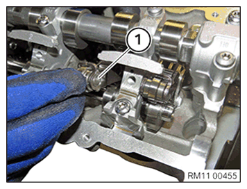
Intermediate lever
NOTE:
TECHNICAL INFORMATION
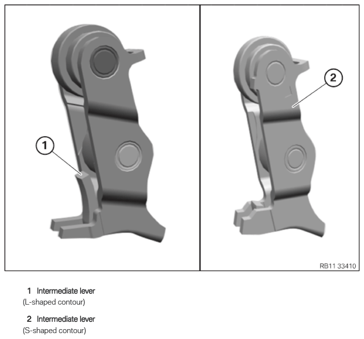
When replacing one or more intermediate levers:
When removing the intermediate lever, it is imperative to note the part number of the intermediate lever.
A mixed installation of intermediate levers is only permitted in combination with the appropriate torsion spring.
For further information on possible combinations, see the applicable BMW parts catalogue.
NOTE:
The description is for one component only. The procedure is identical for all further components.