Checking all cylinders for loss of pressure
High-voltage system.
The high-voltage system operates on the basis of hazardous, electrical voltage and high currents. Danger to life through electric shock!
- All work on the high-voltage system may only be carried out by specially trained and technically experienced personnel.
- For additional information see:
- For additional information see:
Damage to the engine.
The engine may be damaged if it is manually rotated in the wrong direction.
- Turn the combustion engine exclusively by hand in the correct direction of rotation: a) Clockwise, facing the vibration damper or b) Counter-clockwise, facing the chain drive, (b) only applies when the rear timing chain is installed.
Before checking the loss of pressure in the cylinders, it is essential to adjust/calibrate special tool 2 302 630 .
The TDC finder from special tool 2 302 630 must be in the vertical position because otherwise the measuring result may be distorted.
Preliminary work:
- Refer to REMOVING THE ACOUSTIC COVER .
- Refer to REMOVING RESONATOR .
- Refer to REMOVING CLEAN AIR PIPE .
- Refer to REMOVING CHARGE AIR LINE .
- Refer to REMOVING THE ACOUSTIC COVER FOR THE ENGINE AT THE FRONT .
- Refer to REMOVING THE SERVICE OPENING IN SOUND INSULATION ON TOP OF ENGINE .
- Refer to REMOVING IGNITION COILS .
- Refer to REMOVING ALL SPARK PLUGS .
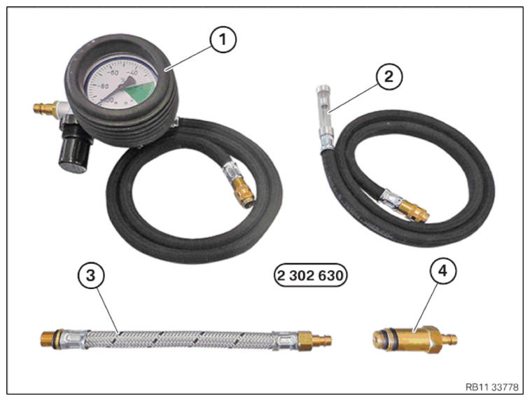
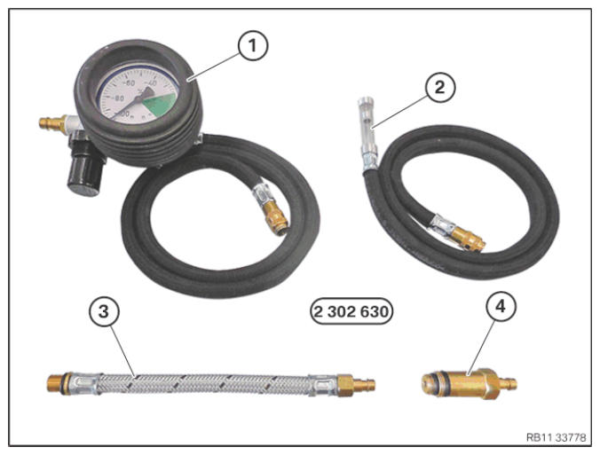
Special tool 2 302 630
Damage to the engine.
If the engine is manually rotated in the wrong direction of rotation, the engine can be damaged.
- Only rotate the engine manually in the correct direction of rotation: a) clockwise when looking at the damper, or b) counterclockwise when looking at the chain drive, b) applies only if the timing chain is installed in the rear.
Before the loss of pressure of the cylinders is checked, the special tool 2 302 630 must be adjusted or calibrated.
- Keep set of special tools 2 302 630
at hand:
Number Description 1 Pressure gauge 2 OT Finder 3 Adapter for the spark plug thread (60) 4 Adapter for the spark plug thread - Have the special tool 0 493 380 (11 6 480) 2 468 560
ready.
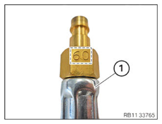
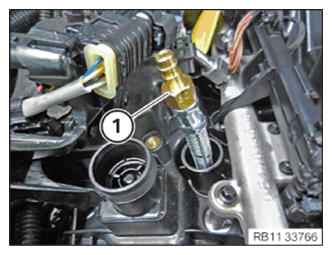
- Have the adapter for the spark plug thread (60) (1) ready.
- Screw in the adapter for the spark plug thread (60) (1) into the spark plug thread by hand.
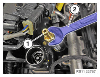
- Tighten the adapter for the spark plug thread (60) (1) with a standard tool (2).
- Connect the OT finder (1) to the adapter for the spark plug thread (60) (2).
The OT finder (1) must engage audibly.
NOTE: TECHNICAL INFORMATION
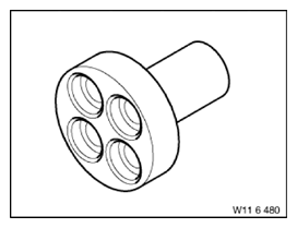
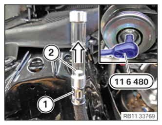
The OT finder from the special tool 2 302 630 absolutely must be vertical, otherwise the measurement result can be falsified. - Fit special tool 0 493 380 (11 6 480) .
- Turn the engine by hand with the special tool 0 493 380 (11 6 480)
.
If the piston goes upwards, the bubble level (2) in the cylinder tube (1) also goes upward in the arrow direction .
- Turn the piston to TDC
.
At TDC , both the piston and bubble level (2) are at the highest point in the cylinder tube (1).
Valves are closed.
NOTE: TECHNICAL INFORMATION
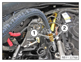
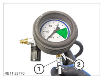
Before the loss of pressure of the cylinders is checked, the special tool 2 302 630 must be adjusted or calibrated. - Connect the quick-release coupling (1) to the valve block (2) of the pressure gauge in the arrow direction
.
The quick-release coupling (1) must engage audibly.
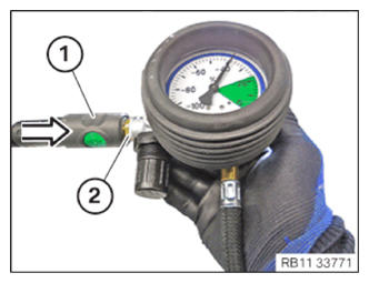
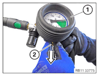
- Connect the compressed air hose (1) to the valve block (2) of the pressure gauge in the arrow direction
.
The compressed air hose (1) must engage audibly.
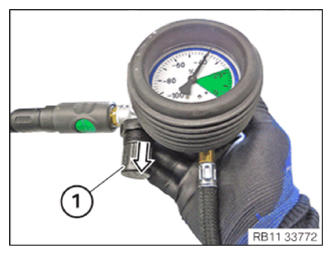
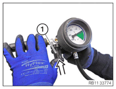
- Unlock the pressure control valve (1) in the.
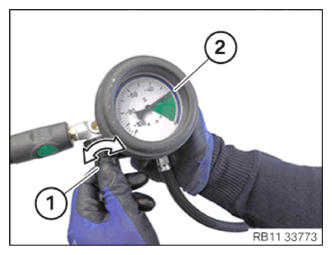
- Turn the pressure control valve (1) in the arrow direction
until the needle (2) of the pressure gauge is at 22%.
- Lock the pressure control valve (1) in the arrow direction.
The pressure control valve (1) must engage audibly.
- Unlock and release the quick-release coupling (2) on the valve block of the pressure gauge (2) in the arrow direction.
- Connect and lock the quick-release coupling (1) of the pressure gauge to the adapter for the spark plug thread (60) (2).
The quick-release coupling (1) of the pressure gauge must engage audibly.
Check
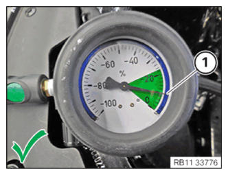
NOTE: The description is provided only at one cylinder. The procedure is the same for all other cylinders. - Read off the loss of pressure; the needle (1) of the pressure gauge must be within the green
area of 0-22%.
Result
The needle (1) of the compressed air pressure gauge is in the green area of 0-22%.
Measure
- Assemble engine.
Check
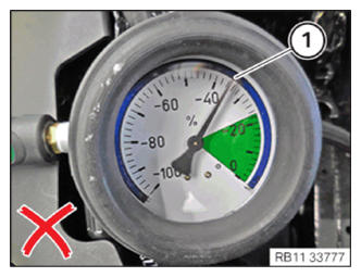
- Read off the loss of pressure. The needle (1) of the pressure gauge must be within the green
area of 0-22%.
Result
The needle (1) of the compressed air pressure gauge is not in the green area of 0-22%.
Measure
- Check possible fault causes and for a piston ring leak (crankcase ventilation) at the intake valves (intake port) or exhaust valves (exhaust system).
Follow-up work:
- Refer to INSTALLING ALL SPARK PLUGS .
- Refer to INSTALLING THE IGNITION COILS .
- Refer to INSTALLING THE SERVICE OPENING IN SOUND INSULATION ON TOP OF ENGINE .
- Refer to INSTALLING THE ACOUSTIC COVER FOR THE ENGINE AT THE FRONT .
- Refer to INSTALLING CHARGE AIR LINE .
- Refer to INSTALLING CLEAN AIR PIPE .
- Refer to INSTALLING RESONATOR .
- Refer to INSTALLING ACOUSTIC COVER .