Installing cylinder head cover
NOTE:
RISK OF DAMAGE
Improper routing of cables and wiring harnesses.
Trapped, crushed or damaged cables may cause short circuits and malfunctions.
Improper routing of cables and wiring harnesses.
Trapped, crushed or damaged cables may cause short circuits and malfunctions.
- Route all cables without abrasions, do not trap and crush.
NOTE:
TECHNICAL INFORMATION
Depending on the build level, different cylinder head covers and therefore different profile seals can be fitted.
Identify suitable cylinder head cover in the applicable BMW parts catalogue and perform the corresponding variant of the work steps.
Depending on the build level, different cylinder head covers and therefore different profile seals can be fitted.
Identify suitable cylinder head cover in the applicable BMW parts catalogue and perform the corresponding variant of the work steps.
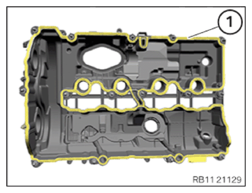
- Version with a profile seal:
Replace the profile seal (1).
Parts: Profile seal
Insert and install the profile seal (1).
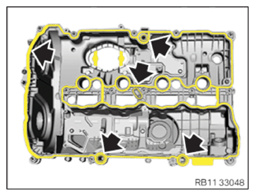
- Version with multiple profile seals:
Replace the profile seals (arrows).
Parts: Profile seals
Insert and install the profile seal (1).
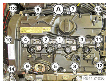
NOTE: TECHNICAL INFORMATION
When assembling, it is essential to observe screwing sequences and tightening torques.
Failure to comply with the regulations can lead to leaks and damage. - Guide in and install the cylinder head cover (A).
- Tighten screws in the order (1) to (15).TIGHTENING TORQUES SPECIFICATION
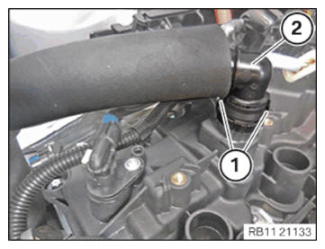
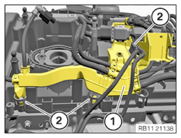
Cylinder head cover to cylinder head M6x30 Joining torque: 8 Nm Tightening torque: 10 Nm - Insert and install the engine ventilation line (2).
- Ensure that the locking mechanisms (1) engage audibly.
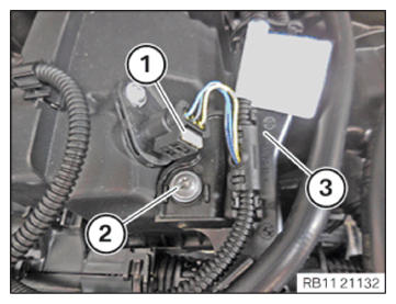
- Guide in and install the wiring harness section (3) for sensor system 1.
- Tighten down screw (2).TIGHTENING TORQUES SPECIFICATION
Wiring harness section for engine to cylinder head cover M6 Tightening torque:
8 Nm - Connect and lock the connector (1) on the intake camshaft sensor.
- Make sure the connector (1) engages audibly on the intake camshaft sensor.
- Connect and lock connector (1) on the exhaust camshaft sensor.
- Make sure the connector (1) engages audibly on the exhaust camshaft sensor.
- Secure clamps (2).
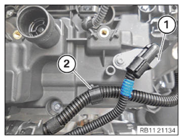
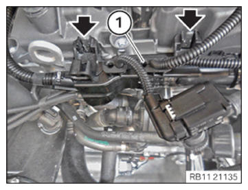
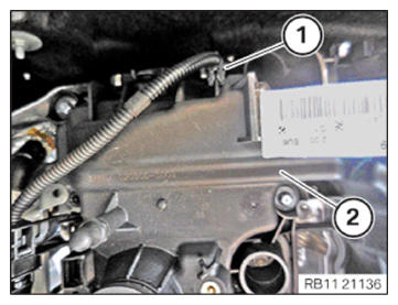
- Feed in and install the wiring harness section (1) for sensor system 2.
- Make sure that you can hear the locks (arrows) engage.
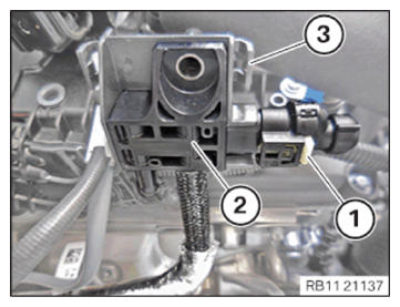
- Feed in and install the differential pressure sensor (2) at the holder (3).
- Connect connectors (1) and lock.
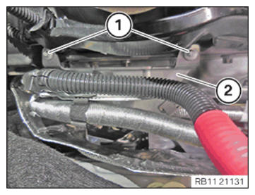
- Make sure the connector (1) engages audibly.CAUTION: Improper routing of the positive battery cable.
Risk of short circuits!- Route the positive battery cable without abrasions and do not trap.
- Feed in the bracket (2) of positive battery cable and install.
- Tighten down screws (1).TIGHTENING TORQUES SPECIFICATION
Holder, positive battery cable to cylinder head cover 6X18 Tightening torque:
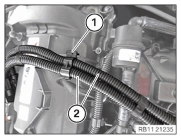
6 Nm - Feed in and install the wiring harness section (1) for sensor system 2 from the guides (2).
- Secure clamps (1).
- Guide in and Install the wiring harness section (2) for the injectors and ignition coils.
- Secure clamps (1).
Follow-up work:
- Refer to INSTALLING BOTH ACTUATORS .
- Refer to PREPARING THE INJECTORS FOR INSTALLATION .
- Refer to INSTALLING THE RAIL WITH INJECTORS .
- Refer to INSTALLING HIGH PRESSURE PUMP .
- Refer to INSTALLING THE HIGH-PRESSURE LINE BETWEEN THE HIGH-PRESSURE PUMP AND THE HIGH-PRESSURE RAIL .
- Refer to INSTALLING FUEL DELIVERY LINE .
- Refer to INSTALLING ALL IGNITION COILS .
- Refer to INSTALLING THE CYLINDER HEAD COVER ACOUSTIC COVER .
- Refer to INSTALLING THE ACOUSTIC COVER FOR THE ENGINE AT THE FRONT .
- Refer to INSTALLING CHARGE AIR LINE .
- Refer to INSTALLING RESONATOR .
- Refer to INSTALLING CENTER BULKHEAD LOWER PART .
- Refer to INSTALLING LEFT SEALING FRAME .
- Refer to INSTALLING ACOUSTIC COVER AT REAR .
- Refer to FASTENING HIGH-VOLTAGE CABLES ON THE ELECTRICAL MACHINE ELECTRONICS .
- Refer to INSTALLING THE CENTER COWL UPPER PART .
- Refer to INSTALLING TENSION STRUT ON SPRING STRUT DOME .
- Refer to INSTALLING WINDSHIELD PANEL COVER .
- Refer to INSTALLING LEFT AND RIGHT WIPER ARM .
- Refer to INSTALLING THE REAR RIGHT ENGINE COMPARTMENT COVER .
- Refer to INSTALLING THE COVER OF THE ENGINE COMPARTMENT ON THE REAR LEFT .
- Refer to CONNECTING ALL BATTERY GROUND LEADS .
- Refer to INSTALLING ACOUSTIC COVER .
- Refer to INSTALLING THE FRONT HOOD SEAL AT THE REAR .
- Refer to TAKING HOOD OUT OF THE SERVICE POSITION .