Move the engine to the mounting orientation
Preliminary work:
- Refer to BRINGING FRONT COMPARTMENT LID IN THE SERVICE POSITION .
- Refer to DEACTIVATING THE 48 V ELECTRICAL SYSTEM .
- Refer to DISCONNECTING ALL BATTERY GROUND LEADS .
- Refer to REMOVING THE ACOUSTIC COVER .
- Refer to REMOVING RESONATOR .
- Refer to REMOVING THE COVER ON LEFT AND RIGHT IN THE ENGINE COMPARTMENT AT THE TOP .
- Refer to REMOVING THE MOUNTING OF THE HOOD SEAL .
- Refer to REMOVING THE SEAL FOR THE HOOD REAR .
- Refer to REMOVING THE COVER OF THE REAR RIGHT ENGINE COMPARTMENT .
- Refer to REMOVING THE COVER OF THE ENGINE COMPARTMENT AT THE REAR LEFT
- Refer to REMOVING LEFT AND RIGHT WIPER ARM .
- Refer to REMOVING THE COWL COVER .
- Refer to REMOVING TRAILING LINK AT SPRING BOLT .
- Refer to REMOVING THE COWL UPPER PART IN THE CENTER .
- Refer to REMOVING ACOUSTIC COVER AT REAR .
- Refer to REMOVING THE IGNITION COILS .
- Refer to REMOVING FUEL DELIVERY LINE .
- Refer to REMOVING REAR UNDERBODY PROTECTION .
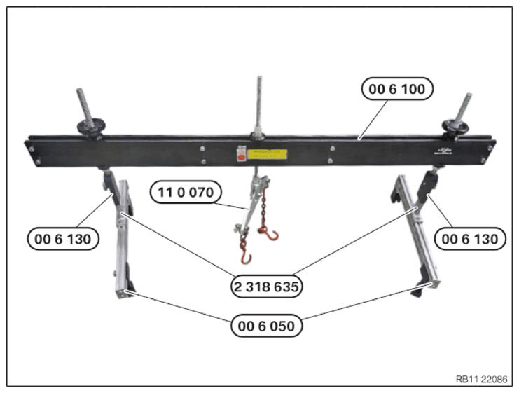
Prepared engine bridge
CAUTION:
Components connected to the engine joint or cross member.
Injury hazard!
Injury hazard!
- Check lifting eyes and engine mounting brackets for damage, e.g. cracks.
- Attach the component to correctly mounted engine joints or cross members only.
- Only lift the component, do not shift it forwards, backwards or in transverse direction.
NOTE:
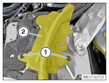
Perform the steps on the right and left side.
- Loosen the rivet (1).
- Remove the lateral hood seal (2) from the shock tower.
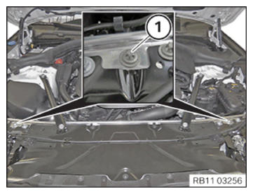
- Release the screws (1) left and right.
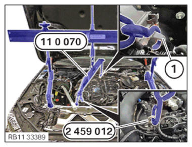
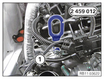
- Guide in and position special tool 2 459 012 on cylinder head.
- Tighten the screws (1) of special tool 2 459 012 .
TIGHTENING TORQUES SPECIFICATION
| Special tool to cylinder head | ||
| M8 | Tightening torque | 21.5 Nm |
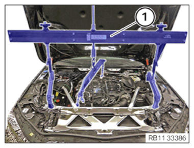
- Carefully
position engine bridge (1) with help from an auxiliary person.
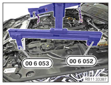
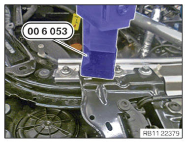
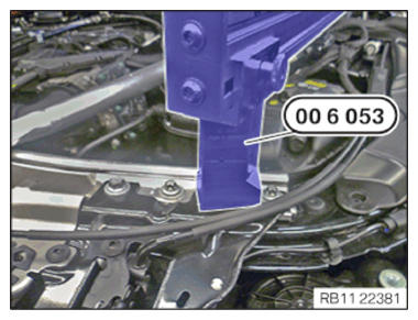
- Make sure that special tool 0 496 438 (00 6 053) on the left lies correctly on the cross connection.
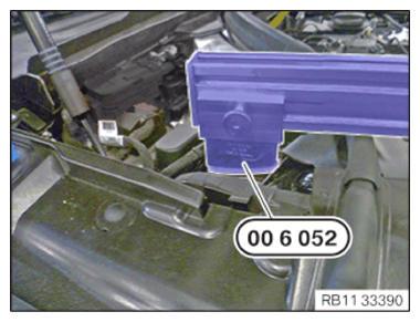
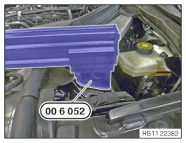
- Make sure that special tool 0 496 437 (00 6 052) on the left
is correctly positioned on the spring strut dome.
- Make sure that special tool 0 496 438 (00 6 053) on the right lies correctly on the cross connection.
- Make sure that special tool 0 496 437 (00 6 052) on the right
is correctly positioned on the spring strut dome.
- Align the engine bridge by moving it on the profile strips of the special tool 0 496 430 (00 6 050) above the engine mounting bracket and screw it down.
- Connect the special tool 0 490 579 (11 0 070) to the special tool 2 459 012 .
- Connect the special tool 0 490 579 (11 0 070)
above the engine mounting bracket (1) at the rear.
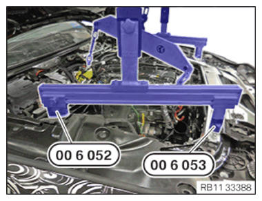
- Check whether the special tool 0 496 438 (00 6 053) on the right
is correctly positioned on the cross connection.
- Check whether the special tool 0 496 437 (00 6 052) on the right
lies correctly on the shock tower.
- Check whether the special tool 0 496 438 (00 6 053) on the left
is correctly positioned on the cross connection.
- Check whether the special tool 0 496 437 (00 6 052) on the left
lies correctly on the shock tower.
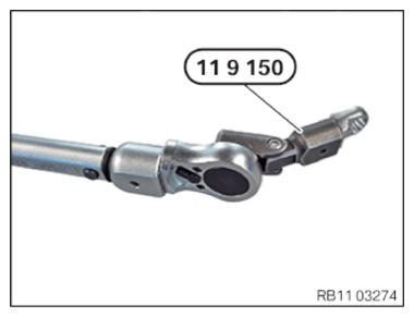
- Prepare special tool 0 493 751 (11 9 150)
as shown.
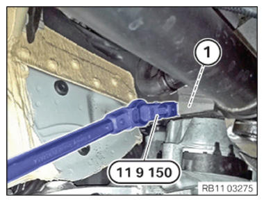
- Release screw (1) on left engine support bracket using special tool 0 493 751 (11 9 150)
from the bottom.
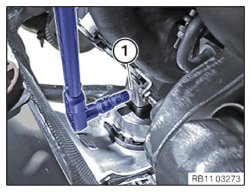
- Release the screw (1) on the engine support bracket on the right from the top.
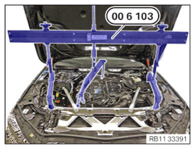
- Lift the engine by turning special tool 2 361 506 (00 6 103)
10 mm.