Installing the engine bridge
NOTE:
DANGER
High-voltage system.
The high-voltage system operates on the basis of hazardous, electrical voltage and high currents. Danger to life through electric shock!
High-voltage system.
The high-voltage system operates on the basis of hazardous, electrical voltage and high currents. Danger to life through electric shock!
- All work on the high-voltage system may only be carried out by specially trained and technically experienced personnel.
- For additional information see:
- For additional information see:
Preliminary work:
- Refer to BRINGING FRONT COMPARTMENT LID IN THE SERVICE POSITION .
- Refer to REMOVING THE ACOUSTIC COVER .
- Refer to REMOVING THE COVER ON THE LEFT AND RIGHT IN THE TOP ENGINE COMPARTMENT .
- Refer to REMOVING THE COVER OF THE REAR RIGHT ENGINE COMPARTMENT .
- Refer to REMOVING THE COVER OF THE ENGINE COMPARTMENT AT THE REAR LEFT
- Refer to REMOVING REAR STIFFENING PLATE .
- Refer to REMOVING THE UNDERBODY PROTECTION OF THE STEERING GEAR AND FRONT STIFFENING PLATE RESPECTIVELY .
- Refer to REMOVING REAR UNDERBODY PROTECTION .
- Refer to REMOVING THE UNIVERSAL JOINT ON THE STEERING GEAR .
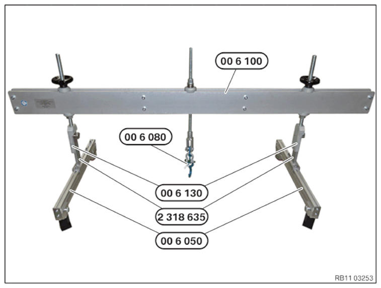
Prepared engine bridge
CAUTION:
Components connected to the engine joint or cross member.
Injury hazard!
Injury hazard!
- Check lifting eyes and engine mounting brackets for damage, e.g. cracks.
- Attach the component to correctly mounted engine joints or cross members only.
- Only lift the component, do not shift it forwards, backwards or in transverse direction.
NOTE:
Perform the steps on the right and left side.
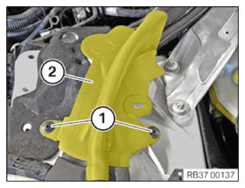
- Loosen the rivet (1).
- Remove the lateral hood seal (2) from the shock tower.
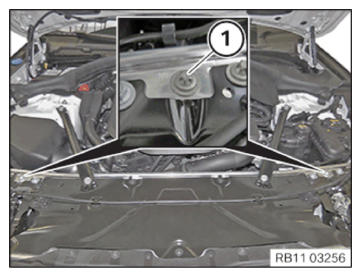
- Release the screws (1) left and right.
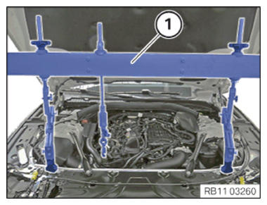
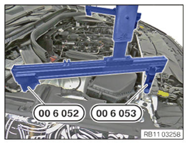
- Carefully position engine bridge (1) with help from an assistant.
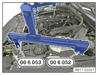
- Make sure that the special tool 0 496 438 (00 6 053) from the set of special tools 0 496 430 (00 6 050) , left, rests correctly on the lock support.
- Make sure that special tool 0 496 437 (00 6 052)
from the set of special tools 0 496 430 (00 6 050)
, left, rests correctly on the shock tower.
- Make sure that the special tool 0 496 438 (00 6 053) from the set of special tools 0 496 430 (00 6 050) , right, rests correctly on the lock support.
- Make sure that special tool 0 496 437 (00 6 052)
from the set of special tools 0 496 430 (00 6 050)
, right, rests correctly on the shock tower.
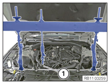
- By shifting the engine bridge on the profile strips of the special tool 0 496 430 (00 6 050) , align it above the engine mounting bracket (1) and screw in place.
- Align hook 0 496 733 (00 6 080) above engine mounting bracket (1).
- Connect hook 0 496 733 (00 6 080)
to engine mounting bracket (1).