Replacing rear timing case cover
Replacement: Remount crankshaft sensor
- For timing case cover replacements:
Remount crankshaft sensor.
NOTE:
RISK OF DAMAGE
Electrostatic discharge.
Damage to or destruction of electrical components.
Electrostatic discharge.
Damage to or destruction of electrical components.
- Leave the electrical components in their original packaging until they are being installed. Only use the original packaging for returning the product. Always package removed components straight away.
- Read and comply with user information on using the associated special tool 12 7 060.
- Only tap the housings of electrical components. Do not tap pins or multipin connectors directly.
- Wear electrically conductive clothing and antistatic shoes (with ESD symbol).
- For additional information see: NOTES ON ESD (ELECTROSTATIC DISCHARGE) PROTECTION
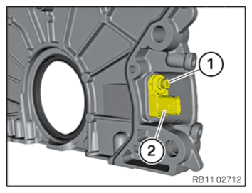
- Loosen the screw (1) and remount the crankshaft sensor (2).
- Tighten down screw (1).
TIGHTENING TORQUES SPECIFICATION
| Crankshaft sensor to timing case cover | ||
| Tightening torque | 4.6 Nm | |
NOTE:
RISK OF DAMAGE
Damage to the surface.
The use of metal-cutting tools (e.g., emery cloths) for cleaning surfaces can damage them and lead to leaks and/or engine damage.
Damage to the surface.
The use of metal-cutting tools (e.g., emery cloths) for cleaning surfaces can damage them and lead to leaks and/or engine damage.
- Do not use any metal-cutting tools.
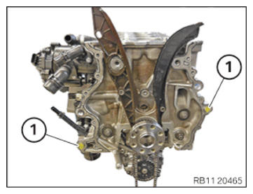
- Remove the seal residue in areas (1) using special tool 0 495 102 (11 4 470) .
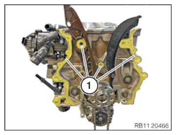
- Check the fitting sleeves (1) for damage and replace as needed.
- Check for correct fit of fitting sleeves (1).
NOTE:
TECHNICAL INFORMATION
For additional information see: OVERVIEW OF CONSUMABLES (BMW PARTS CATALOGUE)
For additional information see: OVERVIEW OF CONSUMABLES (BMW PARTS CATALOGUE)
NOTE:
TECHNICAL INFORMATION
The processing time of the liquid sealing compound can be at a maximum of 10 min.
Commissioning of the assembly is not possible until 25 minutes after the processing time.
Non-observance can lead to leaks in the assembly.
The processing time of the liquid sealing compound can be at a maximum of 10 min.
Commissioning of the assembly is not possible until 25 minutes after the processing time.
Non-observance can lead to leaks in the assembly.
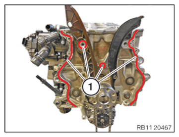
- Apply the sealing compound in area (1) along the inner edge.
SEALING COMPOUND DESCRIPTION
| Loctite 5970 liquid sealing compound Processing time <10 minutes at room temperature |
50 ml, Cartridge | 83190404517 |
TECHNICAL DATA - HEIGHT OF SEALING BEAD SPECIFICATION
| Height of the sealing bead |
| 2.0 mm... 2.5 mm |
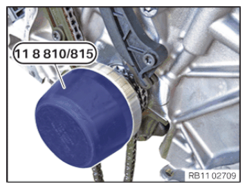
- Mount special tool 0 496 137 (11 8 815)
and 0 496 132 (11 8 810)
on the crankshaft.
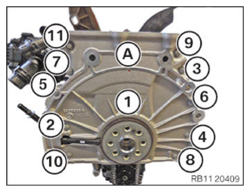
- Replace screws (1) to (11).
Parts : Screws
- Carefully mount the new timing case cover (A).
- Tighten the screws in order from (1) to (11).
TIGHTENING TORQUES SPECIFICATION
| Rear timing case cover on crankcase | ||
| M6 x 31 Replace screws. |
Joining torque Angle of rotation |
8 Nm 90° |
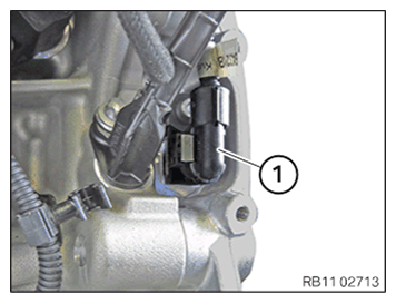
- Connect and lock the connector (1).
- Make sure the connector (1) engages audibly.
Follow-up work
- Refer to REFITTING ENGINE OIL PAN .
- Refer to INSTALL BEARING BRACKET
- Refer to INSTALL FRONT AXLE DIFFERENTIAL
- Refer to INSTALLING THE ACOUSTIC COVER FOR THE OIL SUMP .
- Refer to INSTALLING THE FLYWHEEL .
- Refer to BLOCKING THE CRANKSHAFT IN THE TDC FIRING POSITION OF CYLINDER 1 .
- Refer to SEAL THE OIL DUCT .
- Refer to CLEAN SEALING SURFACES .
- Refer to REPLACE CYLINDER HEAD GASKET .
- Refer to INSTALLING THE CYLINDER HEAD .
- Refer to ADJUSTING THE CAMSHAFTS WITH THE SPECIAL TOOL .
- Refer to INSTALL EXHAUST CAMSHAFT ADJUSTER .
- Refer to INSTALLING THE INTAKE ADJUSTER .
- Refer to INSTALLING THE VANOS CENTRAL VALVE OF THE INTAKE ADJUSTER .
- Refer to INSTALLING THE VANOS CENTRAL VALVE OF THE EXHAUST CAMSHAFT ADJUSTER .
- Refer to PRE-TENSIONING THE TIMING CHAIN WITH THE SPECIAL TOOL .
- Refer to TIGHTENING THE VANOS CENTRAL VALVE OF THE EXHAUST CAMSHAFT ADJUSTER .
- Refer to TIGHTENING THE VANOS CENTRAL VALVE OF THE INTAKE ADJUSTER .
- Refer to DISASSEMBLING ALL SPECIAL TOOLS
- Refer to INSTALL CHAIN TENSIONER .
- Refer to CHECKING THE TIMINGS OF THE CAMSHAFT .
- Refer to INSTALLING THE OIL RETURN LINE FOR THE EXHAUST TURBOCHARGER .
- Refer to INSTALL THE COOLANT RETURN LINE FOR THE EXHAUST TURBOCHARGER .
- Refer to INSTALLING COOLANT FEED LINE FOR EXHAUST TURBOCHARGER .
- Refer to INSTALLING THE HEAT SHIELD ON THE CYLINDER HEAD
- Refer to INSTALLING CYLINDER HEAD COVER .
- Refer to INSTALLING BOTH ACTUATORS .
- Refer to PREPARE THE INJECTORS FOR INSTALLATION .
- Refer to INSTALLING THE RAIL WITH INJECTORS .
- Refer to INSTALLING HIGH PRESSURE PUMP .
- Refer to INSTALLING THE HIGH-PRESSURE LINE BETWEEN THE HIGH-PRESSURE PUMP AND THE HIGH-PRESSURE RAIL .
- Refer to INSTALLING ALL SPARK PLUGS .
- Refer to INSTALL INTAKE PLENUM .
- Refer to INSTALLING THE TANK VENT VALVE .
- Refer to TOPPING UP THE MOTOR OIL .
- Refer to CHECK/ADD FRONT AXLE TRANSMISSION OIL .
- Refer to REMOVING THE ENGINE FROM ASSEMBLY JIG
- Refer to INSTALL ENGINE .