Drive Axle Bearing, Replacing
- Clutch, engaging bearing and slave cylinder removed. Refer to DUAL CLUTCH, REMOVING AND INSTALLING .
-- With the Puller - Crankshaft/Power Steering Seal: T20143 carefully remove the seal -arrow- from the housing.
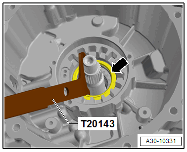
-- A waved washer -arrow- is located behind the seal, it does not need to be replaced.
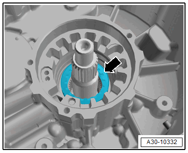
- Pay attention to the installation position of the waved washer!
Drive out the input shaft needle bearing 1.
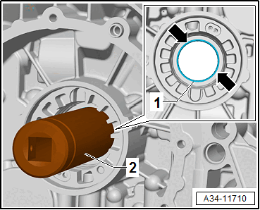
2 - Counterhold Tool: T10114
- Remove the locking ring -Item : Circlip beforehand.
Make sure that the Counterhold Tool: T10114 -2- only in contact with the needle bearing -arrows- and not the housing edges.
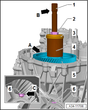
Drive in the input shaft needle bearing 1
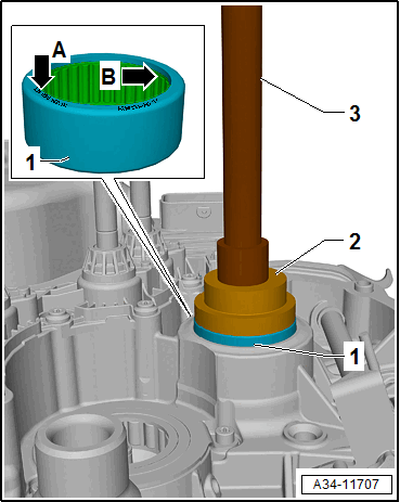
2 - Bearing Installer - Wheel Bearing/Ball Bearing: 3074
3 - Bearing/Bushing Installer - Multiple Use: VW295A
- Installation position: labeling of the bearing -arrow A- (thicker wall thickness -arrow B-) points to the Bearing Installer - Wheel Bearing/Ball Bearing: 3074 -2-.
-- Then insert the needle bearing circlip -Item : Circlip.
-- Install the input shaft seal. Refer to INPUT SHAFT SEAL, REPLACING, CLUTCH HOUSING .
Slide off the output gear 1 of the spur gear unit from the pinion.
 Courtesy of AUDI OF AMERICA, LLC
- Remove the hydraulic pressure reservoir. Refer to GEAR ACTUATOR MODULE AND HYDRAULIC PRESSURE RESERVOIR, REMOVING AND INSTALLING - Vehicles with Self-Locking Center Differential .
- Beforehand, remove the circlip -Item : Circlip from the pinion.
2 - Press Piece - Output Shaft Gear/Final Drive Gear: 3002
3 - Puller (Kukko 18/2): VAS 251 419
4 - M14 x 1.5 Nut or M14 x 1.5 Wheel Nut
-- Attach the Puller -3- to the output gear -1- for the spur gear unit using the nuts -4-.
-- Warm the output gear -1- for the spur gear unit to approximately 100 °C (212 °F) using the Hot Air Blower.
-- Counterhold on the Puller -arrow- when removing.
Risk of damaging the transmission housing.
- The Puller must not contact a housing rib with the nuts -4-.
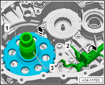
Detach the parking lock gear
- Vehicles with self-locking center differential: remove inner output shaft. Refer to Inner Output Shaft Roller Bearing, Removing, Vehicles with Self-Locking Center Differential .
-- Release the lever for the parking lock -2- in the -direction of the arrow-, using pliers.
-- Remove the parking lock gear -1- upward from the pinion -3-.
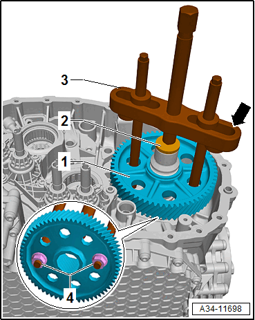
Install the spur gear unit output gear 5
1 - Spindle from Puller (Kukko 18/2): VAS 251 419
2 - Nut
3 - Thrust bearing from Subframe Bushing Tool Kit: 3301
4 - Press Piece - Trailing Arm: 2010
- Beforehand, place the gear for the parking lock -Item : Parking Lock Gear on the pinion.
- Installation position of the gear for the parking lock: the high collar points to the spur gear unit output gear.
- Output gear installation position: the reinforcement ridges -arrow A- face upward.
-- Install the nut -6- (M12) with the washer until the threads are flush.
- The total height of the nut -6- and the washer must not be more than 12 mm.
- The spindle -1- and the nut -6- must not contact the clutch housing -arrow C-.
- Vehicles with self-locking center differential: pay attention to the inner self-locking center differential!
-- Warm the output gear of the spur gear unit -5- using the Inductive Heater: VAS 6414 to approximately 120 °C (248 °F) and on the pinion in the installation position.
-- Then press on over the nut -2- of the output gear of the spur gear unit -5-. At the same time counterhold on the hex fitting -arrow B- of the spindle -1-.
Determine the circlip for the output gear of the spur gear unit on the pinion
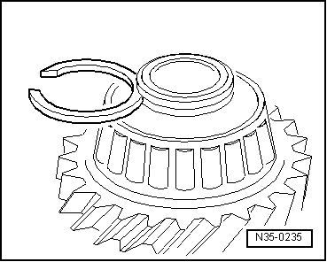
Tip:
- The output gear for the spur gear unit is pressed all the way on.
- The illustration shows a different component. However, determining the circlip is identical.
-- Determine the thickest (but still usable) circlip and insert it. For the part number, refer to the Parts Information.
The following circlips are available:
| Circlip thickness (mm) | ||
|---|---|---|
| 3.85 | 3.90 | 3.95 |
| 4.00 | 4.05 | 4.1 |