Cylinder Head, Removing And Installing: Removing
- During installation, all cable ties must be installed at the same location.
- Always seal off any open channels of the intake and exhaust tract with suitable plugs, for example from the Engine Bung Set: VAS6122 .
-- Remove the camshafts. Refer to CAMSHAFT, REMOVING AND INSTALLING .
-- Remove the Throttle Valve Control Module -GX3-. Refer to Throttle Valve Control Module -GX3-, REMOVING AND INSTALLING .
-- Drain the coolant. Refer to DRAIN THE COOLANT .
Audi A8/Q7/Q8:
-- Remove the Secondary Air Injection Pump Motor -V101-. Refer to Secondary Air Injection Pump Motor -V101-, REMOVING AND INSTALLING .
Vehicle with High-Voltage System:
-- Remove the rear coolant pipe. Refer to REAR COOLANT PIPE, REMOVING AND INSTALLING, VEHICLES WITH HIGH-VOLTAGE SYSTEM .
Vehicle without High-Voltage System with Particulate Filter:
-- Remove the front muffler. Refer to FRONT MUFFLER, REMOVING AND INSTALLING .
All except Audi Q7/Q8:
-- Remove the bolt -arrow- from the particulate filter bracket.
Audi A8:
-- Remove the right subframe shield upper section. Refer to SUBFRAME SHIELD, REMOVING AND INSTALLING .
Vehicles with a Particulate Filter:
-- Remove the bolt -arrow- from the catalytic converter bracket.
Continuation for All Vehicles:
-- Place a cloth underneath to catch leaking engine oil.
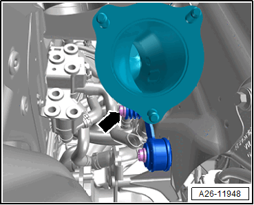
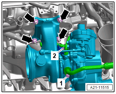
-- Remove the bolt -arrow- and then remove the oil return line.
-- Remove the bolts -arrows- and remove the connection -2-.
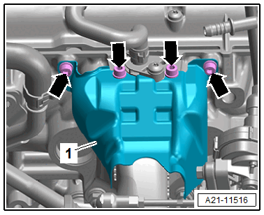
-- Remove the bolts -arrows- and remove the heat shield -1-.
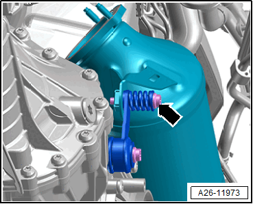
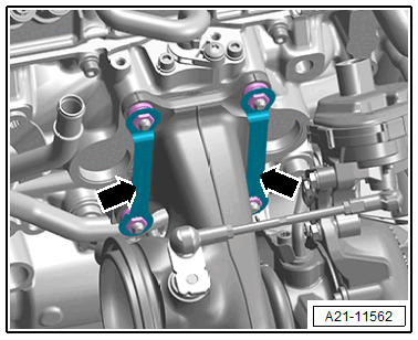
-- Pry out the locking plates -arrows- and dispose.
-- Remove the bolts -1 and 2- and also the oil supply line and the coolant line.
-- Remove the nuts -arrows- and remove the turbocharger from the threaded pins.
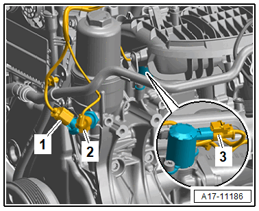
Vehicles with Secondary Air System:
-- Disconnect the connector -2-.
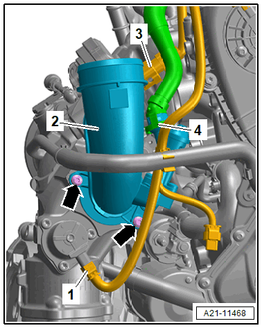
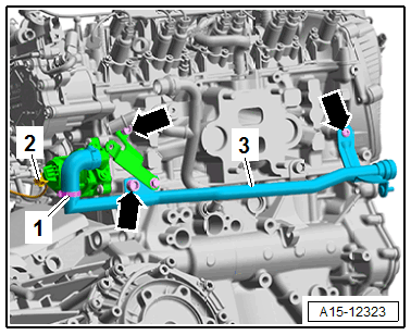
-- Remove the bolts -arrows-.
-- Remove the hose clamp -1- and the secondary air injection pipe -3-.
Right Coolant Pipe, Version 1:
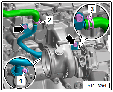
-- Remove the right coolant pipe bolts -arrows-.
Right Coolant Pipe, Version 2:
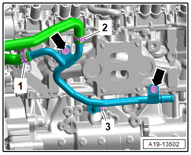
-- Remove the right coolant pipe bolts -arrows-.
Continuation for All Vehicles:
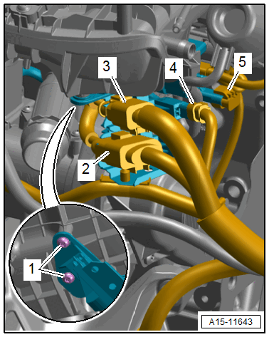
-- Remove the connectors -2 and 3- from the bracket and disconnect.
-- Disconnect the connectors -4 and 5-.
-- Remove the bolts -1- from the bracket.
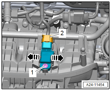
-- Disconnect the connector -2- for the Intake Air Temperature Sensor -G42- / Manifold Absolute Pressure Sensor -G71-.
-- Disconnect the connectors:
- For the Oil Pressure Switch -F22-
- For the Reduced Oil Pressure Switch -F378-
- For the Piston Cooling Nozzle Control Valve -N522-
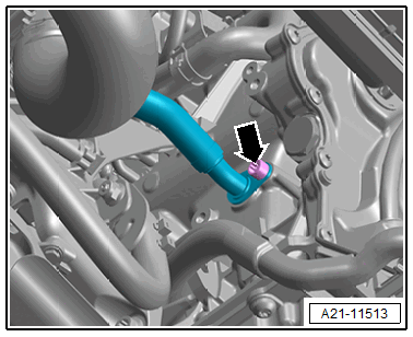
-- Loosen the hose clamp -1- and remove the rear coolant hose.
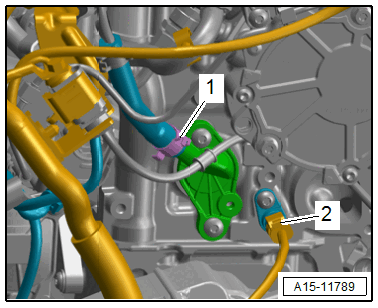
-- Disconnect the connector -2- for the Engine Coolant Temperature Sensor - G62-.
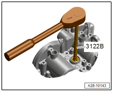
-- Remove the spark plugs with the Spark Plug Removal Tool: 3122B .
-- Remove the bolts -arrows-.
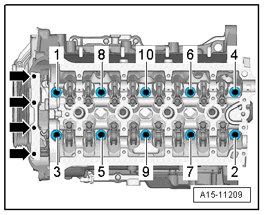
-- Remove the cylinder head bolts using the Socket - XZN 12: T40270 in sequence -1 through 10-.
-- Check if all hose and line connections are loosened.
-- Remove the cylinder head.
-- Lay the cylinder head on a soft surface, such as foam.
-- Seal the open channels of the intake and exhaust tract with clean cloths or with thoroughly cleaned plugs from the Engine Bung Set: VAS6122 .