SUBFRAME Rear Bonded Rubber Bushing, Replacing: Removing
-- Remove the driveshaft from the rear final drive and tie it up. Refer to the appropriate service information .
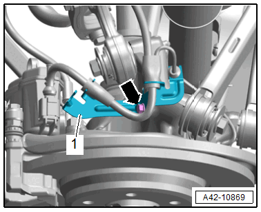
-- Disconnect the left and right connector -arrow- from the rear level control system sensor and free up the wire.
-- Equipped on some models: free up the wires for the Rear Axle Steering Control Module -J1019- and Sway Stabilization Control Module 2 -J1096- on the body.
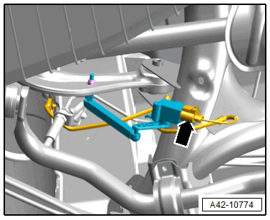
-- Remove the left and right bolt -arrow-, and free up the bracket -1- with the wires.
-- Secure the subframe. Refer to SUBFRAME, SECURING .
-- Lower the subframe a total of a maximum of 100 mm.
-- Pry out the anti-twist mechanism -2- in the area of the retaining tabs with a screwdriver from the bonded rubber bushing alternating from side to side.
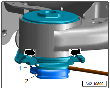
-- Pry out the plastic insert -1- from the bonded rubber bushing.
-- Mark the installation position of the bonded rubber bushing on the subframe -arrows-, for example with a felt-tip pen.
-- If necessary, the support -arrow- with the small interior diameter must be removed from the :VAS6178 and the :T10205/13 must be installed for it.
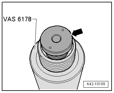
-- Arrange the special tools as shown.
- :T10205/8-1
- :VAS6178
- :T40328/3
- :T40328/1
- :T40373/1 . The conical side must face upward and the ribs must fit into the openings in the rubber bonded bushing
- :T40328/10
- :T10205/8-2
There is a risk of injury from falling components.
- Hold the :VAS6178 firmly while pressing out.
- When pressing off, the bonded rubber bushing loosens abruptly from the subframe. Use, for example, the :VAS6931 to secure.