Sub-Assembly Bracket, Removing And Installing: Removing
-- Drain the coolant. Refer to DRAIN THE COOLANT .
All Except Audi Q7/Q8:
-- Remove the engine cover. Refer to ENGINE COVER, REMOVING AND INSTALLING .
Audi Q7/Q8:
Refer to the appropriate service information.
Audi A6/A7 with High-Voltage System:
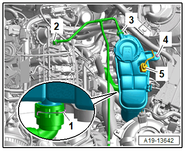
-- Free up the wiring harness.
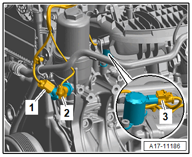
-- Lift the clamps -1, 2 and 3-, remove and free up the coolant hoses.
-- Disconnect the connector -5- for the Engine Coolant Level Sensor -G32-.
-- Remove the bolt -4- and remove the coolant expansion tank.
-- Lift the clamp -1- and remove the coolant hose.
Audi A6/A7 with High-Voltage System and Audi Q5 without High-Voltage System:
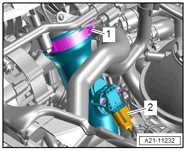
-- Disconnect the connector -2- for the Charge Air Pressure Sensor -G31-.
-- Loosen the screw-type clamp -1- and remove the air duct pipe from the Throttle Valve Control Module -GX3- (example illustration).
-- Seal off any open lines and connections with plugs that are thoroughly cleaned from the Engine Bung Set: VAS6122 .
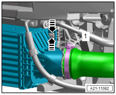
Audi Q5 without High-Voltage System:
-- Remove the left front wheel. Refer to WHEELS AND TIRES .
-- Remove the front left wheel spoiler. Refer to OVERVIEW - FRONT WHEEL HOUSING LINER .
-- Loosen the hose clamp -1- and remove the air duct hose and remove downward.
-- Seal off any open lines and connections with plugs that are thoroughly cleaned from the Engine Bung Set: VAS6122 .
Vehicle without High-Voltage System:
-- Remove the ribbed belt. Refer to RIBBED BELT, REMOVING AND INSTALLING .
Audi A4/A5/A6/A7/Q5:
-- Remove the starter generator. Refer to GENERATOR, REMOVING AND INSTALLING .
Audi A4/A5/A6/A7:
-- Remove the A/C compressor. Refer to A/C COMPRESSOR, REMOVING AND INSTALLING .
Audi A8/Q5/Q7/Q8:
-- Remove the A/C compressor with the refrigerant hoses still connected from the bracket and tie it up on the left side. Refer to A/C COMPRESSOR, REMOVING AND INSTALLING FROM BRACKET .
Audi A8/Q7/Q8:
-- Remove the generator. Refer to GENERATOR, REMOVING AND INSTALLING .
Continuation for All Vehicles:
-- Disconnect the connectors and free up the wires.
- For the Oil Pressure Switch -F22-
- For the Reduced Oil Pressure Switch -F378-
- For the Piston Cooling Nozzle Control Valve -N522-
-- Free up the wires.
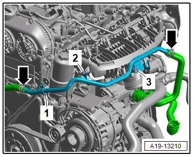
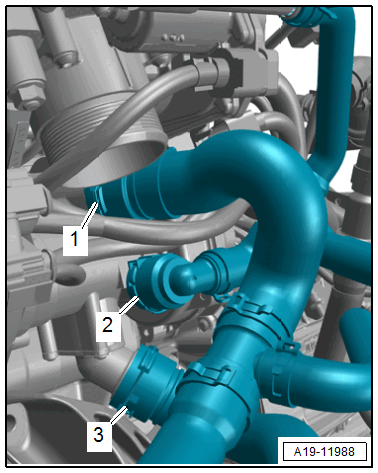
-- Remove the bolts -1, 2 and 3- and pivot the left coolant pipe upward.
-- Remove the oil filter element. Refer to ENGINE OIL .
-- Free up the wires.
-- Place a cloth under the sub-assembly bracket to catch any escaping engine oil.
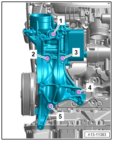
-- Remove the bolts -1 through 5- and pull off the sub-assembly bracket from the coolant pump housing.