Battery -A- / RADIO / FUSES / WIRING HARNESSES OVERVIEW
- A -
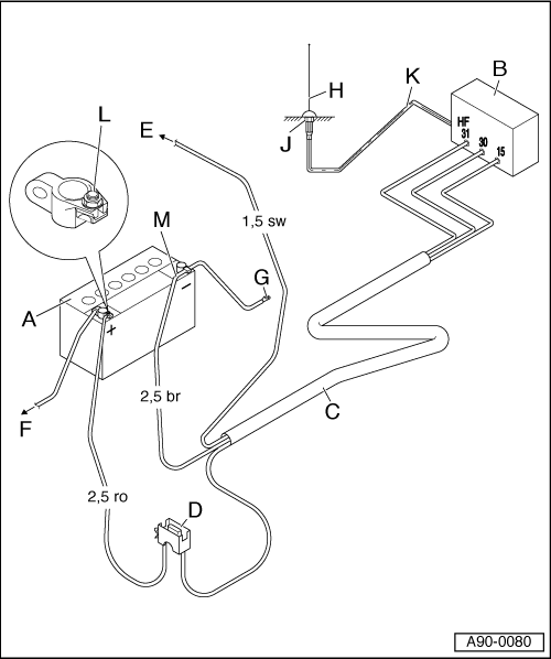
Battery -A-
- Installation position, Disconnecting. Refer to BATTERY, DISCONNECTING AND CONNECTING .
- B -
Radio, Telephone
- Installation position, removing and installing. Refer to COMMUNICATION .
- C -
Wiring Harness
- Must be made
- Positive wire (terminal 30) 2.5 diameter, red
- Ground wire (terminal 31) 2.5 diameter, brown
- Positive wire (terminal 15a) 1.5 diameter, black
- D -
Fuse Panel
- Next to the Battery -A-
- E -
Terminal 15a
- Always clipped on terminal 15a output
- Wire must be protected
- Fuse maximum 15 A
- F -
To the Starter -B-
- Standard wire
- G -
Body Ground
- Directly next to the Battery -A-
- H -
Transmitting/Receiving Antenna
- For required antenna component locations and transmitting powers, refer to the tables. Refer to TRANSMITTER POWER OUTPUT AND ANTENNA COMPONENT LOCATIONS, A1 FROM MY 2011 THROUGH MY 2012 .
- J -
Antenna Ground
- Proper and durable connection/corrosion protection
- K -
Shielded Antenna Wire
- Wire with coaxial connector
- L -
Positive Connection
- Secure red wire with cable shoe A6-2.5 under the nut
- If possible, route wiring harness separately
- M -
Negative Wire
- Secure brown wire with cable shoe A6-2.5 under the nut
- If possible, route wiring harness separately