Tightening the VANOS central valve
NOTE:
Assemble the tools for releasing and tightening of the VANOS central valves according to their accessibility.
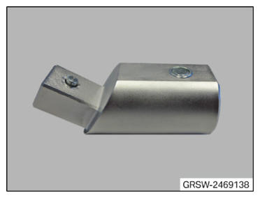
- Have the special tool 2 469 138
ready.
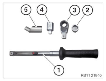
- Have all the special tools and commercially available tools ready.
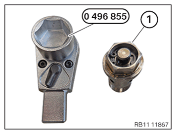
Number Description 1 Standard torque wrench 2 Wrench socket set 2 450 487 3 Reversible ratchet 0 496 855 4 Commercially available reduction 5 adapter 2 469 138 - Assemble all the special tools and commercially available tools as shown.
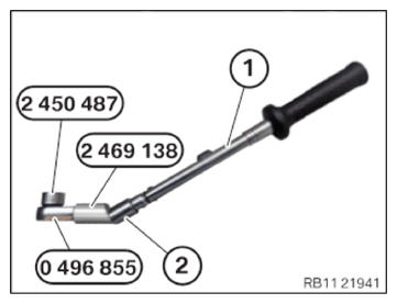
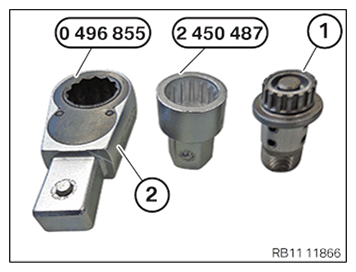
- Use the reversible ratchet (2) from the special tool 0 496 855 with the special tool 2 450 487 to tighten the VANOS central valve (1).
- Use special tool 0 496 855
to tighten the VANOS central valve (1).
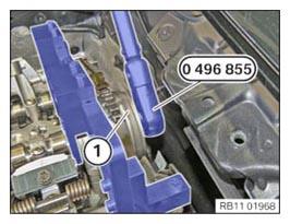
- Tighten the VANOS central valve of the intake adjuster (1) with special tool 0 496 855 or 2 450 487.
TIGHTENING TORQUES SPECIFICATION
| VANOS central valve to camshaft | ||
| M12 x 1 | 1. Joining torque | 30 Nm |
| 2. Joining torque | 50 Nm | |
| 3. Angle of rotation | 65° | |
| M21 VANOS central valve on the thread and on the contact surface must be coated with engine oil. | 1. Joining torque | 50 Nm |
| 2. tightening torque | 140 Nm | |
| M22 VANOS central valve on the thread and on the contact surface must be coated with engine oil. | 1. Joining torque | 50 Nm |
| 2. tightening torque | 140 Nm | |
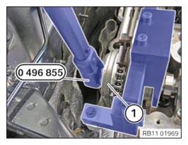
- Tighten VANOS central valve of the exhaust camshaft adjuster (1) with the special tool 0 496 855.
TIGHTENING TORQUES SPECIFICATION
| VANOS central valve to camshaft | ||
| M12 x 1 | 1. Joining torque | 30 Nm |
| 2. Joining torque | 50 Nm | |
| 3. Angle of rotation | 65° | |
| M21 VANOS central valve on the thread and on the contact surface must be coated with engine oil. | 1. Joining torque | 50 Nm |
| 2. tightening torque | 140 Nm | |
| M22 VANOS central valve on the thread and on the contact surface must be coated with engine oil. | 1. Joining torque | 50 Nm |
| 2. tightening torque | 140 Nm | |
Follow-up work
- Refer to CRANKING ENGINE TWICE (AUTOMATIC TRANSMISSION) .
- Refer to DISASSEMBLING ALL SPECIAL TOOLS .
- Refer to INSTALLING CYLINDER HEAD COVER .
- Refer to INSTALLING BOTH ACTUATORS .
- Refer to PREPARING THE INJECTORS FOR INSTALLATION .
- Refer to INSTALLING THE INJECTORS FOR THE CYLINDERS 4 TO 6 .
- Refer to INSTALLING THE INJECTORS FOR THE CYLINDERS 1 TO 3 .
- Refer to PREPARING FOR THE INSTALLATION OF THE HIGH PRESSURE PUMP .
- Refer to INSTALLING HIGH PRESSURE PUMP .
- Refer to INSTALLING FUEL DELIVERY LINE .
- Refer to INSTALLING THE HIGH-PRESSURE LINE BETWEEN THE HIGH-PRESSURE RAIL AND THE HIGH-PRESSURE PUMP .
- Installing all spark plugs. Refer to REPLACING SPARK PLUGS .
- Refer to INSTALLING THE IGNITION COILS .
- Refer to INSTALLING FRONT ENGINE ENCAPSULATION .
- Refer to INSTALLING INTAKE SILENCER HOUSING .
- Refer to INSTALLING THE RESONATOR WITH THE TOP CLEAN AIR PIPE .
- Refer to INSTALLING FAN COWL .
- Refer to INSTALLING THE REAR TOP CROSS CONNECTION .
- Refer to INSTALLING FRONT CROSS CONNECTION .
- Refer to INSTALLING FRONT-END STRUT ON LEFT AND RIGHT .
- Refer to INSTALLING THE COVER ON THE LEFT AND RIGHT IN THE ENGINE COMPARTMENT AT THE TOP .
- Refer to INSTALLING CENTER BULKHEAD LOWER PART .
- Refer to INSTALLING THE SEALING FRAME ON LEFT AND RIGHT .
- Refer to INSTALLING ACOUSTIC COVER AT REAR .
- Refer to INSTALLING THE CENTER COWL UPPER PART .
- Refer to INSTALLING TENSION STRUT ON SHOCK TOWER .
- Refer to INSTALLING WINDSHIELD PANEL COVER .
- Refer to INSTALLING LEFT AND RIGHT WIPER ARM .
- Refer to INSTALLING THE COVER OF THE ENGINE COMPARTMENT ON THE REAR LEFT .
- Refer to INSTALLING THE FRONT HOOD SEAL AT THE REAR .
- Refer to INSTALLING STARTER MOTOR .
- Refer to CONNECTING NEGATIVE BATTERY CABLE .
- Refer to CONNECTING THE DIAGNOSTIC SYSTEM FOR POSSIBLE INTEGRATION LEVEL ENCODING AND PROGRAMMING .
- Refer to INSTALLING THE THRUST FIELD .
- Refer to INSTALLING THE FRONT UNDERBODY PROTECTION OR FRONT THRUST FIELD .
- Refer to INSTALLING ACOUSTIC COVER .
- Refer to TAKING HOOD OUT OF THE SERVICE POSITION .
- Refer to CHECKING ENGINE OIL LEVEL .