Installing fuel delivery line
WARNING:
Working on 12 V electrical system.
Risk of short circuits! Risk of fire!
Risk of short circuits! Risk of fire!
- Make sure that there is no charger connected to the jump start terminal in the engine compartment.
- Detach battery ground lead from battery.
- For auxiliary batteries: Detach battery minus cables from all auxiliary batteries.
WARNING:
Working on fuel system.
Risk of fire! Danger of explosion!
Risk of fire! Danger of explosion!
- When working on the fuel system, make sure the workstation has sufficient ventilation, e.g., by means of extraction.
- Tightly seal off open lines and connections; collect any leakage fuel directly at the point of exit.
- No fire, sparks, open flames or smoking.
CAUTION:
On releasing high pressure line, fuel may emerge at high speed.
Injury hazard!
Injury hazard!
- Wear suitable personal protective equipment.
- Before performing any installation work, allow cooling system to cool down to less than 40°C.
- Note warnings on cylinder head cover.
NOTE:
RISK OF DAMAGE
Contaminant or foreign body.
Contamination can result in malfunctions, loss of function or leaks.
Contaminant or foreign body.
Contamination can result in malfunctions, loss of function or leaks.
- Adhere to the utmost cleanliness.
- Protect components from contamination e.g. by covering.
- Close off line connections with seal plugs.
NOTE:
RISK OF DAMAGE
Damage to the ignition coil.
The silicone hose of the ignition coil must not be contaminated by fuel as this can lead to failure of the ignition coil.
Damage to the ignition coil.
The silicone hose of the ignition coil must not be contaminated by fuel as this can lead to failure of the ignition coil.
- When working on the fuel system, cover the ignition coils with suitable materials and remove where required.
- Do not oil or grease the silicone tube of the spark plug socket. Do not use any protection or maintenance products (e.g. silicone spray, rubber care products, rust remover, etc.).
NOTE:
TECHNICAL INFORMATION
Collect and dispose of emerging fluids. Observe country-specific waste disposal regulations.
Collect and dispose of emerging fluids. Observe country-specific waste disposal regulations.
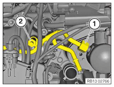
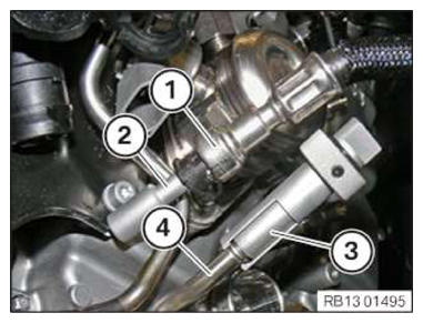
- Tighten the nut (1) at the left high pressure pump.TIGHTENING TORQUES SPECIFICATION
Fuel delivery line to high pressure pump M14 Joining torque 10 Nm Tightening torque 30 Nm - Tighten down screw (2).TIGHTENING TORQUES SPECIFICATION
Fuel supply line to cylinder head cover/cylinder head M6x16 Tightening torque 10 Nm - Feed the fuel supply line in and position it.
- Apply all screw connections only hand-tight .
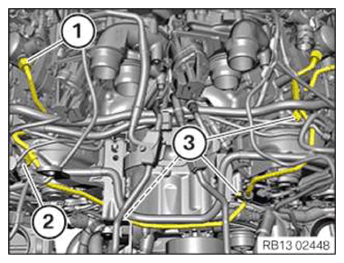
- Tighten the nuts (1) of the fuel supply line on the high pressure pumps.TIGHTENING TORQUES SPECIFICATION
Fuel delivery line to high pressure pump M14 Joining torque 10 Nm Tightening torque 30 Nm - Tighten the screw (2) on the right cylinder head cover.TIGHTENING TORQUES SPECIFICATION
Fuel supply line to cylinder head cover/cylinder head M6x16 Tightening torque 10 Nm - Tighten the screws (3).TIGHTENING TORQUES SPECIFICATION
Fuel supply line to cylinder head cover/cylinder head M6x16 Tightening torque 10 Nm - Tighten down screw (4).TIGHTENING TORQUES SPECIFICATION
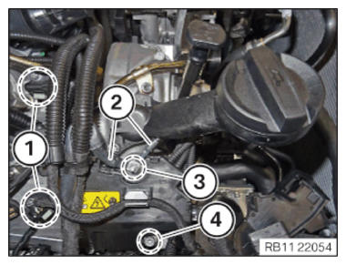
Wiring harness to cylinder head cover M6x16 screw Tightening torque 10 Nm - Position ground cable (2).
- Tighten the nut (3).TIGHTENING TORQUES SPECIFICATION
Ground cable to hold-down device Nuts Tightening torque 5.5 Nm - Connect and lock the connector of the camshaft position sensors (1).
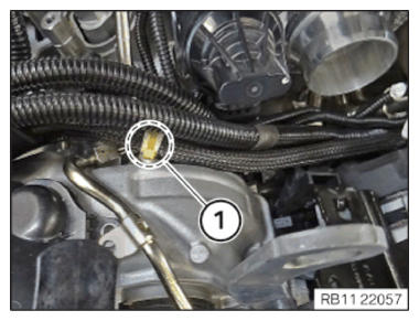
- Clip in the cable clip (1).
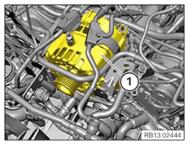
- Carefully insert and install the alternator (1).
- Route the positive battery cable (4) and connect it to the alternator.
- Tighten the nut and mount the cover (1).TIGHTENING TORQUES SPECIFICATION
Positive battery cable to alternator M8 Tightening torque 19 Nm - Fasten the positive battery cable (4) with the clamp (3).
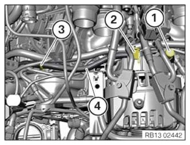
- Connect the connector (2) to the alternator and lock it audibly.
- Connect connectors (1) and lock.
- Connect connectors (4) and lock.
- Position the cable shoe (2).
- Tighten down screws (3).TIGHTENING TORQUES SPECIFICATION
Wiring harness to cylinder head cover M6x16 screw Tightening torque 10 Nm - Tighten the wiring harness in the area (5).
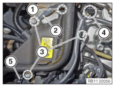
- Tighten the screw in area (1).TIGHTENING TORQUES SPECIFICATION
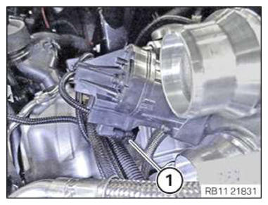
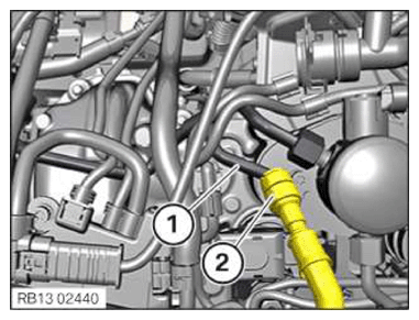
Wiring harness to cylinder head cover M6x16 screw Tightening torque 10 Nm - Disconnect the special tool 0 496 565 (13 5 160) (2) from the fuel line (1).
- Disconnect the special tool 0 496 565 (13 5 160)
(3) from the fuel supply line (4).
- Connect the fuel line to the fuel line (2) to the fuel feed line (1) and lock it audibly.
- Install the safety ring.
Follow-up work
- Refer to INSTALLING THE IGNITION COILS OF CYLINDERS 1 AND 5 .
- Refer to INSTALLING THE CLEAN AIR PIPE OF CYLINDER BANK 2 .
- Refer to INSTALLING CLEAN AIR PIPE OF CYLINDER BANK 1 .
- Refer to INSTALLING BOTH CHARGE AIR COOLERS .
- Refer to INSTALL THE COOLANT EXPANSION TANK FOR THE LOW-TEMPERATURE COOLANT CIRCUIT (CHARGE AIR COOLER) .
- Refer to SEALING OFF COOLANT FOR LOW-TEMPERATURE COOLANT CIRCUIT .
- Refer to INSTALLING THE UNDERBODY PROTECTION OF THE STEERING GEAR OR THE FRONT THRUST FIELD .
- Refer to INSTALL THE FRONT UNDERBODY PROTECTION OR FRONT THRUST FIELD .
- Refer to CONNECTING THE LEFT CHARGE AIR LINE TO THE EXHAUST TURBOCHARGER .
- Refer to INSTALL DRIVE BELT .
- Refer to INSTALLING FAN COWL .
- Refer to INSTALL THE REAR TOP CROSS CONNECTION .
- Refer to INSTALL FRONT CROSS CONNECTION .
- Refer to INSTALLING THE RIGHT INTAKE FILTER HOUSING WITH THE RIGHT FRONT-END STRUT .
- Refer to INSTALLING LEFT INTAKE FILTER HOUSING WITH LEFT FRONT-END STRUT .
- Refer to INSTALLING THE COVER ON THE LEFT AND RIGHT IN THE ENGINE COMPARTMENT AT THE TOP
- Refer to INSTALLING THE CONTROL UNIT BRACKET FOR CYLINDERS 5 TO 8 .
- Refer to INSTALL CLEAN AIR PIPE, TOP .
- Refer to INSTALLING THE COVER OF THE LEFT DME CONTROL UNIT .
- Refer to INSTALLING CONTROL UNIT HOLDER FOR CYLINDERS 1 TO 4 .
- Refer to INSTALLING THE COVER OF THE RIGHT DME CONTROL UNIT .
- Refer to DISCONNECTING ALL BATTERY GROUND LEADS .
- Refer to FILL AND VENT THE LOW-TEMPERATURE COOLANT CIRCUIT .