When replacing the electric heater: Remount components
NOTE:
DANGER High-voltage system. The high-voltage system operates on the basis of hazardous, electrical voltage and high currents. Mortal hazard through electric shock!
- All work on the high-voltage system may only be carried out by specially trained and technically experienced personnel.
- For additional information see: 61 00... SAFETY INSTRUCTIONS on handling hybrid cars
- For additional information see: 61 25... NOTES on repair of high-voltage battery unit
Preliminary work
- Disconnect all battery GROUND LEADS .
- Remove the UNDERBODY PROTECTION/FRONT THRUST FIELD .
- Remove rear UNDERBODY PROTECTION .
- Remove ELECTRIC HEATER .
NOTE:
DANGER Potential equalization in high-voltage system. Mortal hazard if the potential equalization screw connection is not correct!
- Observe the safety requirements for the potential equalization screw connection.
- Clean contact faces and have then checked by a second person.
- Tighten the screws/nuts for potential equalization with torque; have a second person check the torque.
- Correct execution of these tasks must be documented in the vehicle records by both persons.
NOTE:
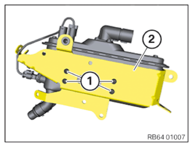
Schematic diagram is for example purposes. Some parts may differ in certain details.
- Loosen screws (1).
- Remove the holder (2).
- If necessary, unclip the cable bracket.NOTE: TECHNICAL INFORMATION
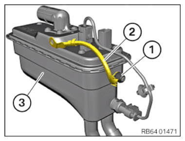
Do not twist the equipotential bonding line. If necessary mark the equipotential bonding line before removal. Pay attention to correct fitting of the equipotential bonding line. - Release nut (1).
- Mark the equipotential bonding line (2) before detaching.
- Replace the nut (1).
Parts: Nut
- Remove the equipotential bonding line (2) from the electric heating (3) and fit correctly onto the new electric heating.
- Tighten nut (1).TIGHTENING TORQUES SPECIFICATION
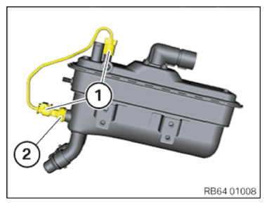
Equipotential bonding line on electrical heating Hexagon nut M6 Tightening torque 4.0 Nm - Unlock and disconnect plug connections (1).
- Remount the coolant temperature sensor (2).
- Connect connectors (1) and lock.NOTE: Schematic diagram is for example purposes. Some parts may differ in certain details.
- Install the holder (2) on the new electric heater.
- Tighten down screws (1).TIGHTENING TORQUES SPECIFICATION
Electrical heating to holder/body Nut M6 Tightening torque 8 Nm Hexagon screw
M6x16Tightening torque 8 Nm Torx screw M6x12 Tightening torque 7.6 Nm - If necessary, clip in the cable bracket.
Follow-up work
- Install ELECTRIC HEATER .
- Reconnect all battery GROUND LEADS .
- Fill the HIGH-TEMPERATURE COOLING SYSTEM with the vacuum filling equipment
- Vent the HIGH-TEMPERATURE COOLANT SYSTEM .
- Check the HIGH-TEMPERATURE COOLING SYSTEM for watertightness.
- Install rear UNDERBODY PROTECTION .
- Install the front UNDERBODY PROTECTION .