Adjust track and camber
Adjustment of camber/track on wishbone
Preliminary work
- PROCEDURE for track and camber adjustment in design position.
- PROCEDURE for adjusting track/camber for ride-height-dependent measurement (unloaded).
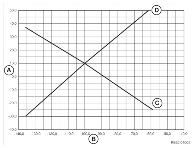
Diagram dependency of track/camber adjustment
(For printing out and entering values)
NOTE:
TECHNICAL INFORMATION
Through the turning of the eccentric screws (setting of camber and track), the vehicle ride height can change. For the exact setting of the camber and track, the automatic ride height measurement should be activated in the wheel alignment equipment when available.
Through the turning of the eccentric screws (setting of camber and track), the vehicle ride height can change. For the exact setting of the camber and track, the automatic ride height measurement should be activated in the wheel alignment equipment when available.
NOTE:
TECHNICAL INFORMATION
Turning the adjustment screw on the camber control arm or on the wishbone always results in a change in the camber and track values! Separate camber or toe adjustment is no longer possible!
Turning the adjustment screw on the camber control arm or on the wishbone always results in a change in the camber and track values! Separate camber or toe adjustment is no longer possible!
NOTE:
TECHNICAL INFORMATION
Check the alignment of the active cruise control (ACC) after an adjustment on the rear axle that changes the driving axis.
Check the alignment of the active cruise control (ACC) after an adjustment on the rear axle that changes the driving axis.
NOTE:
TECHNICAL INFORMATION
Turning the eccentric bolts to adjust toe and camber may change the vehicle ride height. When replacing the screws, make sure the eccentric bolts are correctly positioned to keep the change in vehicle ride height during the adjustment work to a minimum.
Turning the eccentric bolts to adjust toe and camber may change the vehicle ride height. When replacing the screws, make sure the eccentric bolts are correctly positioned to keep the change in vehicle ride height during the adjustment work to a minimum.
- Raise vehicle.
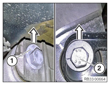
- Replace the eccentric screws (1) and (2) including nut and eccentric washers before setting and join with 5 Nm.
Parts: Eccentric screws, nuts, eccentric washers
- Position the eccentric screws (1) and (2) during replacement so that the eccentric is positioned vertically towards the top.
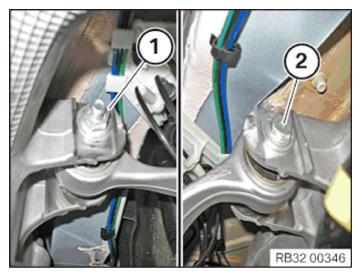
- Adjusting on wishbone:
Turn the eccentric screw (2) until the intermediate setting is in place.
Tighten nut (1).
TIGHTENING TORQUES SPECIFICATIONUpper wishbone to rear axle carrier M14
Replace bolt, nut and eccentric washer.
Tighten in NORMAL POSITION .Tightening torque 175 Nm - Adjusting on camber control arm:
Turn the eccentric screw (2) to adjust to the setpoint value.
Tighten nut (1).
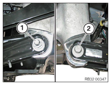
TIGHTENING TORQUES SPECIFICATION
| Camber control arm to rear axle support | ||
| M14 Replace bolt, nut and eccentric washer. Tighten in NORMAL POSITION . |
Tightening torque | 175 Nm |
Follow-up work