Prepare the mobile table lift
WARNING:
Hot surfaces.
Risk of burning!
Risk of burning!
- Perform all work only on components that have cooled down.
WARNING:
Vehicle may slip off the vehicle hoist if the vehicle hoist is handled incorrectly.
Danger! Immobilization period-threatening injuries!
Danger! Immobilization period-threatening injuries!
- Observe safety instructions on raising the vehicle using a vehicle hoist.
- For additional information see: RAISING THE VEHICLE USING A VEHICLE LIFT .
CAUTION:
Component with heavy weight.
Injury hazard!
Injury hazard!
- Note component's center of gravity.
- Support component using a jack.
- Secure component against falling off the jack.
Preliminary work
- Refer to SUCTION THE AIR CONDITIONING .
- Refer to BRINGING FRONT COMPARTMENT LID IN THE SERVICE POSITION .
- Refer to REMOVING BOTH FRONT-END STRUTS .
- Refer to REMOVING FAN COWL .
- Refer to REMOVING THE COVER OF THE COOLING MODULE .
- Refer to DISCONNECTING REFRIGERANT LINES .
- Refer to REMOVING THE FUEL HOSE .
- Refer to PARTIALLY REMOVING TANK VENT LINE .
- Refer to REMOVING THE FRONT LEFT AND RIGHT WHEELS .
- Refer to REMOVING THE FRONT RIGHT LOWER WHEEL ARCH COVER .
- Refer to REMOVING THE LEFT FRONT BOTTOM WHEEL ARCH COVER .
- Refer to REMOVING THE FRONT UNDERBODY PROTECTION OR FRONT THRUST FIELD .
- Refer to REMOVING THE UNDERBODY PROTECTION OF THE STEERING GEAR AND THRUST FIELD RESPECTIVELY .
- Refer to REMOVING THE STIFFENING PLATE .
- Refer to DRAINING COOLANT .
- Refer to DRAINING THE COOLANT FOR THE LOW-TEMPERATURE COOLANT CIRCUIT .
- Refer to REMOVING THE COOLANT HOSE BETWEEN THE COOLANT RADIATOR AND ENGINE .
- Refer to REMOVING THE COOLANT LINE BETWEEN THE COOLANT PUMP AND HEAT EXCHANGER .
- Refer to REMOVING COOLANT HOSE BETWEEN COOLANT RADIATOR AND THERMOSTAT .
- Refer to REMOVING COOLANT PUMP FOR LOW-TEMPERATURE, LEFT .
- Refer to INSTALLING RIGHT COOLANT PUMP FOR LOW TEMPERATURE .
- Refer to DISCONNECTING ALL BATTERY GROUND LEADS .
- Refer to DETACHING B POSITIVE WIRE ON THE JUMP START TERMINAL POINT .
- Refer to RELEASING THE TRANSMISSION WIRING HARNESS PARTIALLY .
- Refer to REMOVING THE COVER PANEL OF THE LEFT DME CONTROL UNIT .
- Refer to REMOVING THE CONTROL UNIT BRACKET FOR CYLINDERS 5 TO 8 .
- Refer to REMOVING THE COVER OF THE RIGHT DME CONTROL UNIT .
- Refer to REMOVING THE CONTROL UNIT BRACKET FOR CYLINDERS 1 TO 4 .
- Refer to REMOVING THE CONNECTING SUPPORT FROM THE TUNNEL .
- Refer to IF INSTALLED: REMOVING THE TORSION STRUT ON THE RIGHT AND LEFT WHERE REQUIRED .
- Refer to REMOVING THE HEAT SHIELDS .
- Refer to COMPLETELY REMOVING THE PROP SHAFT (PLUG-IN - REAR FLEXIBLE DISC) .
- Refer to LOOSENING GROUND STRAP FROM TRANSMISSION .
- Refer to DETACHING COOLANT HOSES FROM THE FRONT AXLE SUPPORT .
- Refer to REMOVING REAR UNDERBODY PROTECTION .
- Refer to REMOVING THE HEAT SHIELD ON THE LEFT TUNNEL .
- Refer to REMOVING THE HEAT SHIELD ON THE RIGHT TUNNEL .
- Refer to REMOVING THE RIGHT ENGINE MOUNT REINFORCEMENT STRUT .
- Refer to DETACHING THE WIRING HARNESS OF THE EPS FROM THE FRONT AXLE SUPPORT .
- Refer to RELEASING THE FRONT LEFT AND RIGHT BRAKE CALIPERS .
- Refer to RELEASING THE BRAKE HOSE AT THE FRONT LEFT AND RIGHT .
- Refer to DETACHING THE CABLE OF THE WHEEL RPM SENSOR ON THE LEFT AND RIGHT .
- Refer to RELEASING CABLE FROM VERTICAL ACCELERATION SENSOR ON LEFT AND RIGHT .
- Refer to IF INSTALLED: DISCONNECTING THE PLUG CONNECTIONS OF THE ACTIVE STABILIZER .
- Refer to RELEASING THE THERMOSTAT OR TRANSMISSION OIL COOLER LINE FROM THE FRONT SUBFRAME .
- Refer to DETACHING COOLANT HOSES FROM THE FRONT AXLE SUPPORT .
- Refer to LOOSENING THE UNIVERSAL JOINT FROM THE STEERING GEAR .
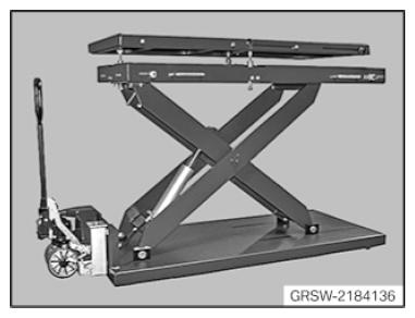
Mobile table lift
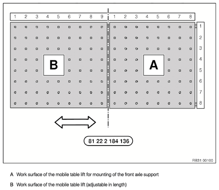
- Stage the mobile table lift 2 184 136
.
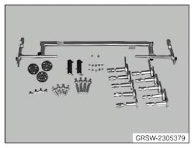
- Place the mounting element from the set of special tools 2 305 379
ready.
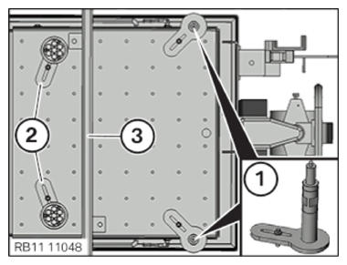
- Position the mounting elements (1) with the mounts (50) on the work surface (A) of the mobile lifting table for the front subframe at the coordinates 7/1 and 7/8 .
- Position the mounting elements (2) with the mounts (80) on the work surface (A) of the mobile lifting table for the front subframe at the coordinates 2/2 and 2/7 .
- Position the swivel bearing stand (3) on the work surface (A) of mobile lifting table at the coordinates 3/1
and 4/8
.
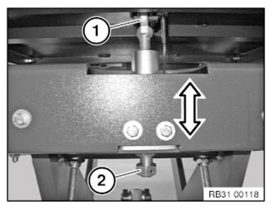
- Adjust the inclination of the lifting table (1) with the adjustment screw (2) until the bubble level of the lifting table (1) displays the correct position.