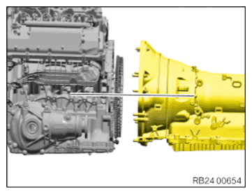
Installing the automatic transmission (all-wheel drive vehicle) (GA8HP75HZ)
NOTE:
RISK OF DAMAGE
Damage to the transmission.
Damage to the transmission due to unapproved transmission oil.
Damage to the transmission.
Damage to the transmission due to unapproved transmission oil.
- Use only the approved TRANSMISSION OIL .
- Check the transmission OIL LEVEL after completing the repair.
NOTE:
TECHNICAL INFORMATION
After completion of the work, program the control unit for the electronic gearbox control (EGS).
After completion of the work, program the control unit for the electronic gearbox control (EGS).
NOTE:
RISK OF DAMAGE
Damage of the flywheel and automatic transmission.
A non-horizontal fit during the removal and installation of the automatic transmission can lead to damage on the automatic transmission or flywheel.
Damage of the flywheel and automatic transmission.
A non-horizontal fit during the removal and installation of the automatic transmission can lead to damage on the automatic transmission or flywheel.
- Align the automatic transmission completely horizontal to the engine during the removal and installation.
- Check for correct alignment before tightening the transmission bolts.
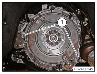
- Align the automatic transmission horizontal to the engine before installation.
- Check for correct fit of lining sleeves (1).
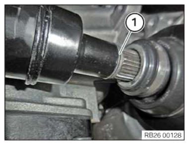
- Before installing the front prop shaft in the transfer box (VTG), replace the O-ring (1).
Parts: O-ring
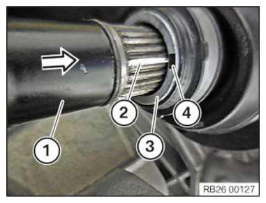
- Position the front prop shaft (1) on the output flange (3) of the transfer box (VTG).
- Align marks (2) and (4).
- Push front prop shaft (1) to stop in output flange (3) of transfer box (VTG).
- Flange-mount the transmission on the transfer box (VTG).
- Replace the bolts (arrows).
Parts: Screws
- Join the bolts (arrows) and hand-tighten.
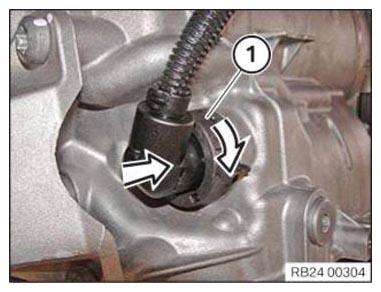
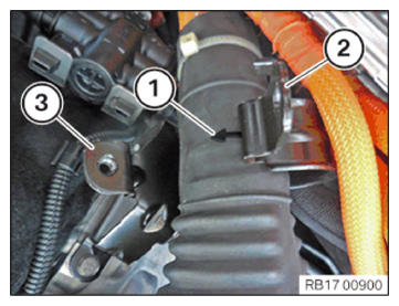
- Remove the special tool 0 494 213 (24 2 390)
in arrow direction from the sealing sleeve (1).
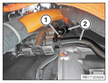
- Slide the connector (1) on and turn it to lock.
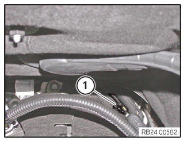
- Connect connectors (1) and lock.
- Install the line (2).
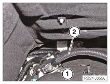
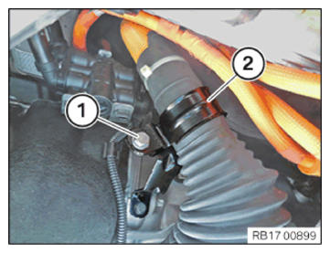
- Connect connectors (1) and lock.
- Install the connector (2).
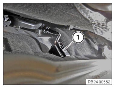
- Replace the screw (1).
Parts: Screw
- Tighten down screw (1).
- Connect connectors (1) and lock.
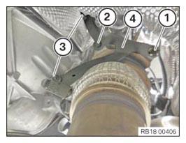
- Insert and install the holder (4).
- Replace screws (3).
Parts: Screws
- Tighten down screws (3).
- Replace the screw (2).
Parts: Screw
- Tighten down screw (2).TIGHTENING TORQUES SPECIFICATION
Catalytic converter to holder M8
Replace screw.Tightening torque 19 Nm - Replace nut (1).
Parts: Nut
- Tighten nut (1).TIGHTENING TORQUES SPECIFICATION
Catalytic converter to holder M8
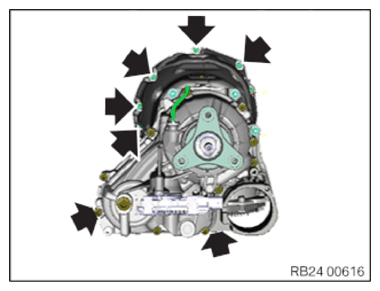
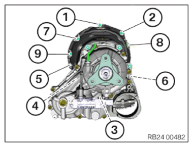
Replace nut.Tightening torque 19 Nm - Tighten screws in the order (1) to (9).TIGHTENING TORQUES SPECIFICATION
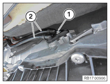
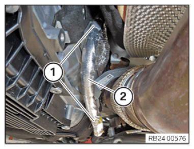
Transmission to engine M8 Tightening torque 19 Nm M12 Tightening torque 66 Nm - Feed in and install transmission oil lines (2).
- Replace the screw (1).
Parts: Screw
- Tighten down screw (1).
- Feed in and install transmission oil lines (2).
- Replace the screw (1).
Parts: Screw
- Tighten down screw (1).
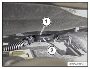
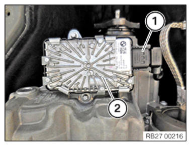
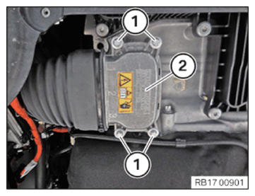
- Connect the connector (1) to the VTG control unit (longitudinal torque distribution) (2).
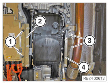
- Insert and install the holder (2).
- Replace screws (1).
Parts: Screws
- Tighten down screws (1).
- Position the high-voltage cable (1) on the holder (3) in the direction of the arrow.
- Insert and install the holder (2).
- Position holder (2).
- Replace the screw (1).
Parts: Screw
- Tighten down screw (1).
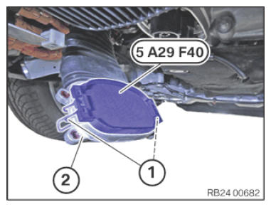
- Unlock the clamps (1).
- Remove the special tool 5 A29 F40
from high-voltage connector (2).
- Guide in and install the high-voltage connector (2).
- Replace screws (1).
Parts: Screws
- Hand-tighten the bolts (1) crosswise up to the high-voltage connector (2).
- Tighten screws (1) crosswise.
- Install holder (3).
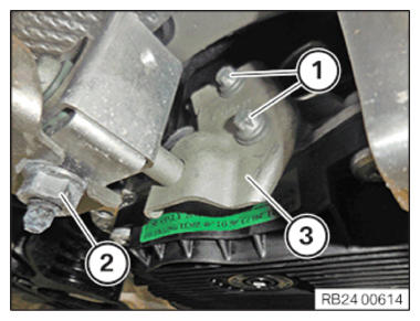
- Replace the bolts (1) and the nut (2).
Parts: Bolts, nut
- Tighten the screws (1) and the nut (2).TIGHTENING TORQUES SPECIFICATION
Front pipe/front silencer/gasoline particulate filter to the transmission holder M8
Replace nut.Tightening torque 19 Nm NOTE: DANGER
Potential equalization in high-voltage system.
Mortal hazard if the potential equalization screw connection is not correct!- Observe the safety requirements for the potential equalization screw connection.
- Clean contact faces and have then checked by a second person.
- Tighten the screws/nuts for potential equalization with torque; have a second person check the torque.
- Correct execution of these tasks must be documented in the vehicle records by both persons.
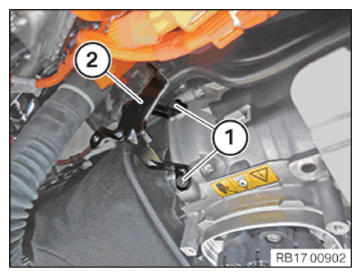
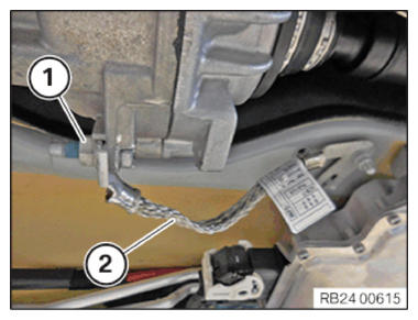
- Install the ground strap (2).
- Replace nut (1).
Parts: Nut
- Tighten nut (1).TIGHTENING TORQUES SPECIFICATION
Ground strap to transmission or body M8 Tightening torque 19 Nm - Clip the positive battery cable (2) into the clamps (1).
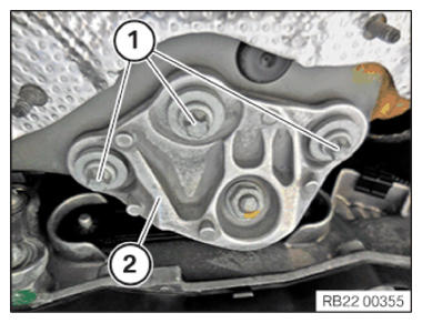
- Replace screws (1).
Parts: Screws
- Tighten the screws (1) on the transmission bearing support (2).TIGHTENING TORQUES SPECIFICATION
Transmission bearing support to body M8 Tightening torque 19 Nm - Install holder (2).
- Replace screws (1).
Parts: Screws
- Tighten down screws (1).TIGHTENING TORQUES SPECIFICATION
Retaining plates for vehicle underbody cover Sheet metal nut/plastic nut Replace nuts. Tightening torque 3 Nm - Install holder (4).
- Replace screws (3).
Parts: Screws
- Tighten down screws (3).TIGHTENING TORQUES SPECIFICATION
Retaining plates for vehicle underbody cover Sheet metal nut/plastic nut Replace nuts. Tightening torque 3 Nm

Follow-up work
- Install the front axle transmission front PROPELLER SHAFT .
- Fasten the (partially removed) PROP SHAFT
- Install transmission CROSS MEMBER .
- Install the HEAT SHIELDS .
- Install the complete EXHAUST SYSTEM .
- If installed: install the right and left TORSION STRUT where required.
- Install the rear axle COVER .
- Install the tunnel connecting SUPPORTS
- Reconnect all battery GROUND LEADS
- Check/top up the automatic transmission OIL LEVEL .
- Install the transmission side UNDERBODY PLANKING .
- Install rear UNDERBODY PROTECTION .
- Activate HIGH-VOLTAGE SYSTEM .
- Install flap in right luggage compartment TRIM PANEL .