Installing the exhaust turbocharger for the cylinders 1 to 4
WARNING:
Hot surfaces.
Risk of burning!
Risk of burning!
- Perform all work only on components that have cooled down.
CAUTION:
Heavy component.
Heavy components can lead to injury or damage.
Heavy components can lead to injury or damage.
- Remove and install heavy components with the aid of another person/other persons.
NOTE:
RISK OF DAMAGE
Contaminant or foreign body.
Contamination can result in malfunctions, loss of function or leaks.
Contaminant or foreign body.
Contamination can result in malfunctions, loss of function or leaks.
- Adhere to the utmost cleanliness.
- Protect components from contamination e.g. by covering.
- Close off line connections with seal plugs.
NOTE:
TECHNICAL INFORMATION
The sealing surfaces must be free of oil, grease and cleaning agents.
The sealing surfaces must be free of oil, grease and cleaning agents.
Prepare for the installation of the exhaust turbocharger
- Check the oil feed and oil return lines for contamination or obstruction and clean or replace as needed.
- If the oil feed and/or oil return lines are heavily contaminated, we recommend changing the motor oil and the oil filter.
- If installed: Check the coolant feed and coolant return lines for the exhaust turbocharger for contamination or obstruction and clean or replace as needed.
- Check the screw connections and plug connections of all lines for accuracy.
- Check air filter for contamination and clean or replace as needed.
- Check correct functioning of crankcase ventilation.
- Replace all gaskets.
Parts: Seals
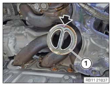
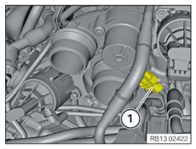
- Replace the seal (1).
Parts: Gasket
- Check the pin (arrow) for damage and replace the exhaust manifold if necessary.
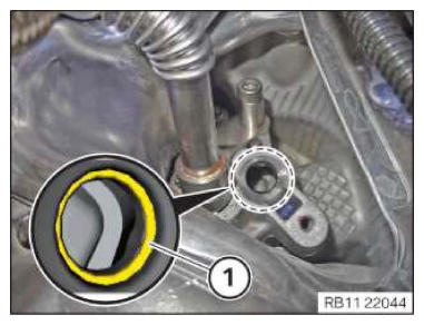
- Make sure that the O-ring (1) does not fall into the oil duct in the engine block.
- Replace O-ring (1).
Parts: O-ring
If the O-ring (1) cannot be disassembled, the oil return lid must be disassembled.
- Coat O-ring (1) with engine oil.
Engine oil
Technically suitable engine oils for BMW Group engines
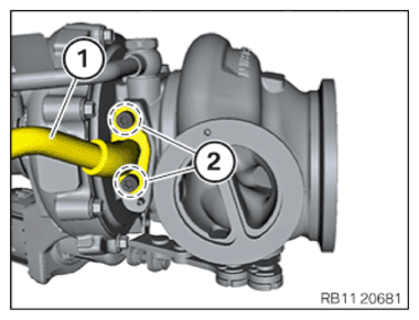
- Loosen screws (2).
- Remove the oil return line (1).
- Ensure that the sealing surfaces in the area of the oil return line are planar and free from oil and grease.
- Replace oil return line (3) after each disassembly of the exhaust turbocharger.
Parts: Oil return line
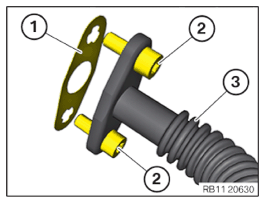
- Replace the seal (1).
Parts: Gasket
- Replace screws (2).
Parts: Screws
- Position screws (2) in oil return line (3).
- Position the seal (1) on the screws (2).
- Position the oil return line (1).
- Screws (2) must be tightened with the aid of an support person.
TIGHTENING TORQUES SPECIFICATION
| Oil return line at the exhaust turbocharger | ||
| M6x16 Replace screws. |
Joining torque | 5 Nm |
| Angle of rotation | 60° | |
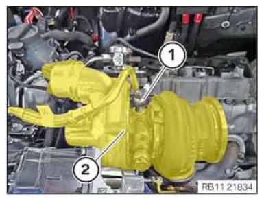
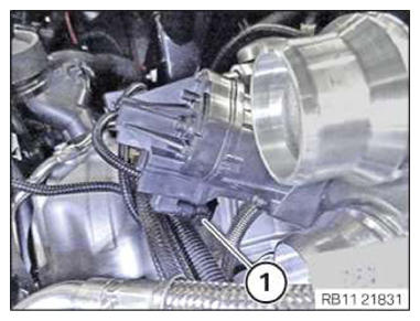
- Feed in and install the exhaust turbocharger (2) at right with the coolant lines and oil return line.
- When installing the right exhaust turbocharger (2), make sure that the oil return line is correctly positioned in the oil return cover.
- Make sure the oil feed line (1) is positioned correctly.
- Fasten the wiring harness mounting (1) to the holder (2).
- Insert the holder (2).
- Tighten down screws (1),
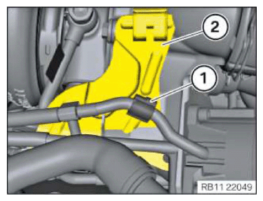
TIGHTENING TORQUES SPECIFICATION
| Holder of sensor system | ||
| M6x16 screw | Tightening torque | 8 Nm |
- Replace the V-clip (2).
Parts: V-band clamp
- Position V-clip (2).
- Tighten down screw (1).
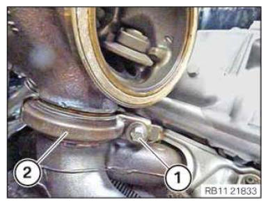
TIGHTENING TORQUES SPECIFICATION
| Exhaust turbocharger to exhaust manifold | ||
| V-band clamp Replace V-band clamp. | Tightening torque | 20 Nm |
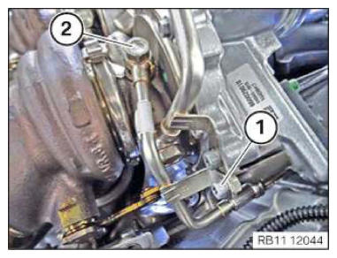
- Tighten the screw (1) on the oil return pipe (2).
TIGHTENING TORQUES SPECIFICATION
| Oil return line to oil return cover | ||
| M6 | Tightening torque | 10 Nm |
- Connect connectors (1) and lock.
The connector (1) must engage audibly.
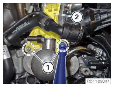
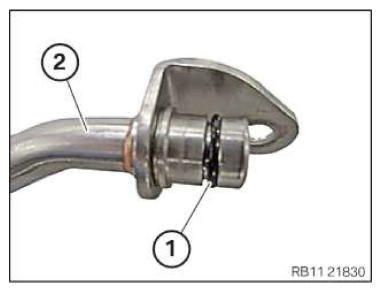
- Replace sealing ring (1) of the coolant line (2).
Parts: Sealing ring
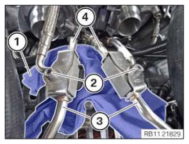
- Connect coolant lines (4).
- Connect coolant lines (3).
- Tighten down screws (2).
TIGHTENING TORQUES SPECIFICATION
| Coolant line from exhaust turbocharger to bracket | ||
| M6x30 | Tightening torque | 8 Nm |
- Remove the lint-free rag (1).
- Connect connectors (1) and lock.
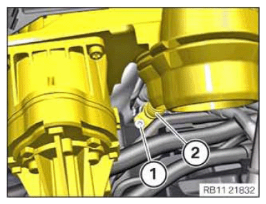
- Replace the screw (1).
Parts: Screw
- Replace the sealing ring or sealing rings (2).
Parts: Sealing ring or sealing rings
- Make sure that when installing sealing rings without a fitting aid (bridge), both sealing rings are replaced.
- Position screw (1) with the sealing ring or sealing rings (2) on the oil feed line.
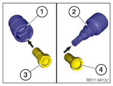
- Determining the screw type and selecting the appropriate socket wrench:
| Screw type | Matching socket wrench |
|---|---|
| Hexagon screw (3) | Commercial socket wrench (1) |
| Multi-tooth screw (4) | Multi-tooth socket wrench (2) |
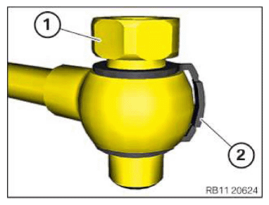
- Screw in the banjo bolt (2) several threads.
- Hand-tighten the bolt (1).
- Tighten the banjo bolt (2).
TIGHTENING TORQUES SPECIFICATION
| Banjo bolt for oil feed line to exhaust turbocharger | ||
| M10x1 Replace the screw and sealing rings. |
Joining torque | 8 Nm |
| Angle of rotation | 70° | |
- Tighten down screw (1).
TIGHTENING TORQUES SPECIFICATION
| Oil feed line to exhaust turbocharger | ||
| M6x16 | Tightening torque | 10 Nm |
Follow-up work
- Refer to INSTALLING CLEAN AIR PIPE OF CYLINDER BANK 1 .
- Refer to INSTALLING THE RIGHT CHARGE AIR LINE .
- Refer to CLOSING THE HIGH-TEMPERATURE COOLANT CIRCUIT .
- Refer to INSTALLING THE UNDERBODY PROTECTION OF THE STEERING GEAR OR THE FRONT THRUST FIELD .
- Refer to INSTALLING THE FRONT UNDERBODY PROTECTION OR FRONT THRUST FIELD .
- Refer to INSTALLING THE FRONT LEFT BOTTOM WHEEL ARCH COVER .
- Refer to INSTALLING THE FRONT BOTTOM RIGHT WHEEL ARCH COVER .
- Refer to INSTALLING FAN COWL .
- Refer to INSTALLING THE REAR TOP CROSS CONNECTION .
- Refer to INSTALLING FRONT CROSS CONNECTION .
- Refer to INSTALLING THE RIGHT INTAKE FILTER HOUSING WITH THE RIGHT FRONT-END STRUT .
- Refer to INSTALLING LEFT INTAKE FILTER HOUSING WITH LEFT FRONT-END STRUT .
- Refer to INSTALLING THE COVER ON THE LEFT AND RIGHT IN THE ENGINE COMPARTMENT AT THE TOP .
- Refer to INSTALLING THE CATALYTIC CONVERTER FOR CYLINDERS 1 TO 4 .
- Refer to RELEASING THE HEAT SHIELD .
- Refer to INSTALLING THE CENTER COW! UPPER PART .
- Refer to INSTALLING TENSION STRUT ON SHOCK TOWER .
- Refer to INSTALLING WINDSHIELD PANEL COVER .
- Refer to INSTALLING LEFT AND RIGHT WIPER ARM .
- Refer to INSTALLING THE REAR RIGHT ENGINE COMPARTMENT COVER .
- Refer to INSTALLING THE COVER OF THE ENGINE COMPARTMENT ON THE REAR LEFT .
- Refer to INSTALLING RIGHT HEAT SHIELD .
- Refer to INSTALLING LEFT HEAT SHIELD .
- Refer to INSTALLING HEAT SHIELD, TOP .
- Refer to INSTALLING THE RIGHT OXYGEN SENSOR MONITOR .
- Refer to INSTALLING THE LEFT OXYGEN SENSOR MONITOR .
- Refer to PARTIALLY INSTALLING THE RIGHT LAMBDA OXYGEN SENSOR .
- Refer to PARTIALLY INSTALLING THE LEFT LAMBDA OXYGEN SENSOR .
- Refer to INSTALLING THE RETAINING BRIDGE .
- Refer to INSTALLING EXHAUST SYSTEM .
- Refer to INSTALLING CENTER REAR UNDERSHIELD .
- Refer to INSTALLING THE CONNECTING SUPPORTS ON THE TUNNEL .