Installing the flywheel
NOTE:
TECHNICAL INFORMATION
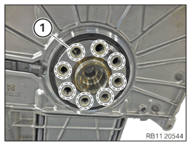
Clean all threads with a screw tap.
Clean all threads with a screw tap.
| Description |
| Twist drill |
| Thread cutter M12x1.5 |
| Deep stop |
| Screw in tool |
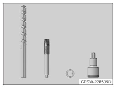
- Assemble tool set.
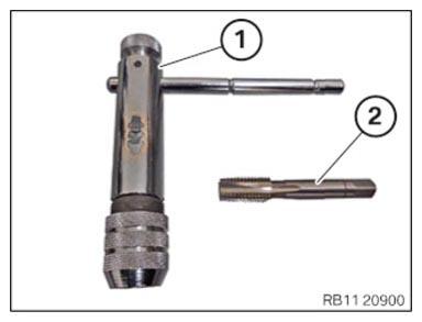
| Number | Description |
|---|---|
| 1 | Tool holder |
| 2 | Thread cutter M12X1.5 |
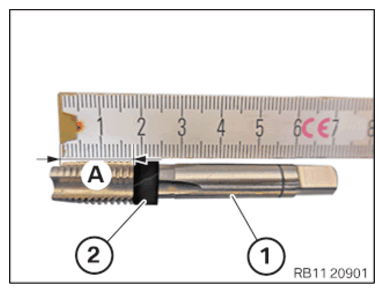
- Mark screwing depth (A) on the thread cutter (1) from the special tool set 2 285 058 with a commercially available tool (2).
TECHNICAL DATA - SCREW-IN DEPTH SPECIFICATION
| Screw-in depth of thread cutter | |
| Screw-in depth | 18 mm |
NOTE:
To provide a better overview: Shown with engine removed.
- Screw in the thread cutter (1) from the set of special tools 2 285 058 in arrow direction up to the screw-in depth (2).
TECHNICAL DATA - SCREW-IN DEPTH SPECIFICATION
| Screw-in depth of thread cutter | |
| Screw-in depth | 18 mm |
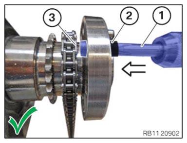
- Make sure that the thread cutter is (1) not pressed up against the timing chain (3).
NOTE:
TECHNICAL INFORMATION
Handle the timing chain carefully to protect the timing chain and timing chain drive from damage.
Handle the timing chain carefully to protect the timing chain and timing chain drive from damage.
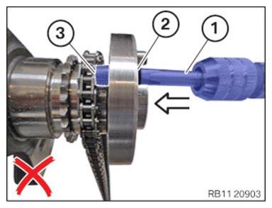
- Make sure that the screw-in depth (2) of the screw tap (1) is not exceeded.
The thread cutter (1) must not come into contact with the timing chain (3).
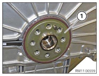
- Note the installation position of the magnet wheel (1).
- Position the magnet wheel (1) on the crankshaft.
- Replace screws (1) to (8).
Parts: Screws
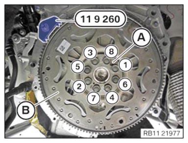
- Position the flywheel (B).
- Screw in flywheel bolt (1) to (8) by hand.
- Set flywheel (B) with the special tool 0 494 034 (11 9 261) and screw tight with the special tool 0 494 130 (11 9 264) .
- Make sure that the tightening sequence takes place from the dowel pin (A).
- Tighten the flywheel bolts in the sequence (1) to (8) (note the angle of rotation in the next step).
TIGHTENING TORQUES SPECIFICATION
| Flywheel to crankshaft | ||
| M12x1.5 Replace screws. |
Tightening torque Angle of rotation |
45 Nm 45° |
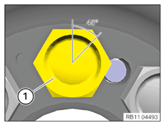
- Apply all flywheel bolts (1) with an angle of rotation of 45° with the help of the special tool 0 490 504 (00 9 120) .
NOTE:
Mark all flywheel bolts (1) with a vertical line.
- Remove special tool 0 493 938 (11 9 260) .
Follow-up work
- Refer to INSTALL AUTOMATIC TRANSMISSION (GA8HP51Z) .
- Refer to INSTALLING STARTER MOTOR .
- Refer to FASTENING THE PROP SHAFT (PARTIALLY REMOVED)
- Refer to INSTALLING TRANSMISSION CROSS MEMBER .
- Refer to INSTALL THE RETAINING PLATES .
- Refer to INSTALLING THE HEAT SHIELDS .
- Refer to INSTALLING THE COMPLETE EXHAUST SYSTEM .
- Refer to INSTALL THE CONNECTING SUPPORTS ON THE TUNNEL .
- Refer to INSTALL FAN COWL .
- Refer to INSTALL THE REAR TOP CROSS CONNECTION .
- Refer to INSTALL FRONT CROSS CONNECTION .
- Refer to INSTALLING BOTH FRONT-END STRUTS
- Refer to INSTALLING THE COVER ON THE LEFT AND RIGHT IN THE ENGINE COMPARTMENT AT THE TOP
- Refer to CONNECTING NEGATIVE BATTERY CABLE .
- Refer to ACTIVATING THE 48 V ELECTRICAL SYSTEM .
- Refer to CHECKING/TOPPING UP THE OIL LEVEL IN THE AUTOMATIC TRANSMISSION .
- Refer to INSTALLING ACOUSTIC COVER .
- Refer to INSTALL REAR UNDERBODY PROTECTION .
- Refer to INSTALL THE CENTER UNDERBODY PROTECTION .
- Refer to INSTALL THE FRONT UNDERBODY PROTECTION OR FRONT THRUST FIELD .
- Refer to TAKE HOOD OUT OF THE SERVICE POSITION .