Assembling the cylinder head
Install all valves
Contaminant or foreign body.
Contamination can result in malfunctions, loss of function or leaks.
- Adhere to the utmost cleanliness.
- Protect components from contamination e.g. by covering.
- Close off line connections with seal plugs.
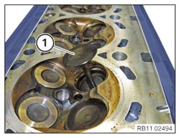
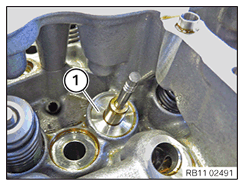
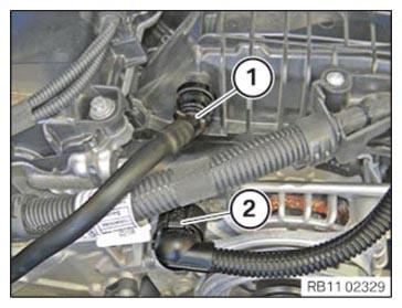
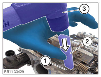
- Slide the valve (1) carefully
in the cylinder head.
- B46/B48:
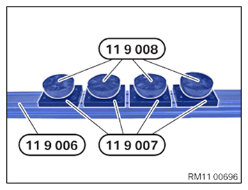
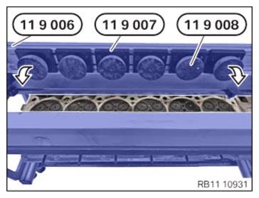
Prepare the special tools 0 494 371 (11 9 006), 0 494 372 (11 9 007) and 0 494 373 (11 9 008) as shown.
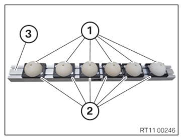
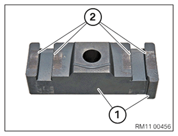
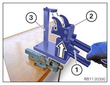
- B58:
Prepare plastic shaped parts (1) with the shaped parts (2) and aluminum frame insert (3).
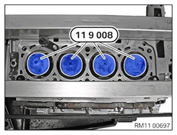
- Version B46/B48:
0 494 373 (11 9 008) for the corresponding alignment in the next step is to be prepared.
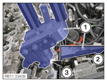
NOTE: TECHNICAL INFORMATION
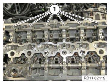
The figure shows the engine B58. - Position the special tools 0 494 371 (11 9 006), 0 494 372 (11 9 007)
and 0 494 373 (11 9 008)
on the cylinder head in the center in arrow direction.
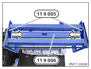
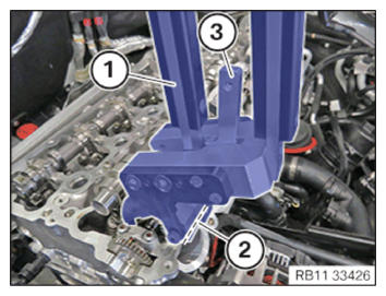
- Turn round special tool 0 494 371 (11 9 006) and insert as shown.
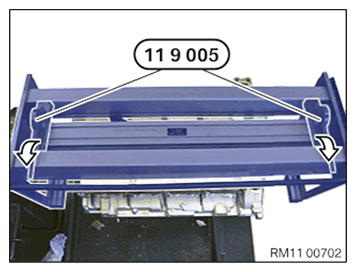
- Lock the special tools 0 494 370 (11 9 005)
in arrow direction.
- Shift the special tools 0 494 370 (11 9 005)
in arrow direction via the edges of the special tools 0 494 371 (11 9 006)
and lock them.
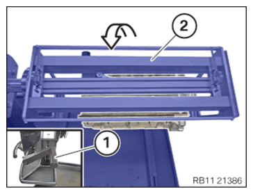
- Turn the special tool 0 494 366 (11 9 001)
(2) on the crank (1) by 180° in arrow direction.
Installing valve stem seals
Contaminant or foreign body.
Contamination can result in malfunctions, loss of function or leaks.
- Adhere to the utmost cleanliness.
- Protect components from contamination e.g. by covering.
- Close off line connections with seal plugs.
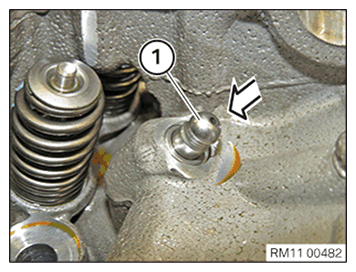
- Remove oil and dirt from the contact surface (1).NOTE: TECHNICAL INFORMATION
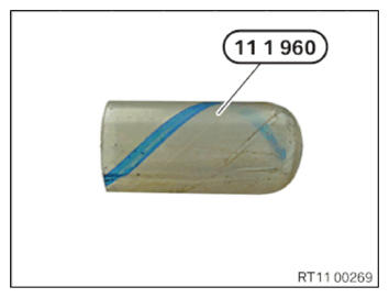
As an alternative to special tool 0 490 797 (11 1 960), the assembly sleeves delivered with the spare part can be used (see the applicable BMW parts catalogue). - Make sure that the special tool 0 490 797 (11 1 960)
or the assembly sleeves are used when installing the valve stem seal.
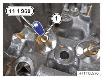
- Guide in and install special tool 0 490 797 (11 1 960)
or assembly sleeves on valve (1).
- Replace the valve stem seal (1) or assembly sleeves.
Parts: Valve stem seal, assembly sleeves
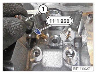
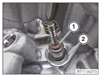
- Guide in and install valve stem seal (1) on special tool 0 490 797 (11 1 960)
or assembly sleeves.
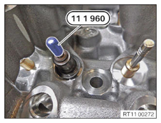
- Guide out and remove special tool 0 490 797 (11 1 960)
or assembly sleeves.
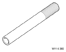
- Prepare special tool 0 493 249 (11 6 380).
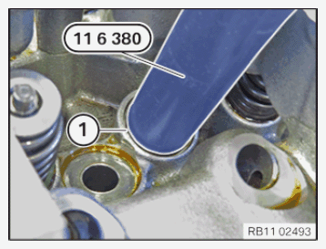
- Press the valve stem seal (1) onto the cylinder head 0 493 249 (11 6 380)
up to the stop using special tool.
- Make sure that the valve stem seal (1) is correctly positioned on the cylinder head (2).
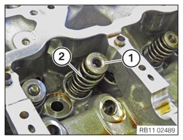
Install valve springs
- Install the valve spring (2) and the spring plate (1).
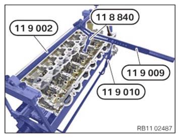
- Mount special tool 0 494 367 (11 9 002).
- Align special tool 0 494 374 (11 9 009) in direction of valve axis. Select the corresponding groove using special tool 0 496 143 (11 8 840).
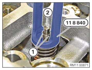
- Press down the valve spring on the spring cup at the top with special tools 0 494 374 (11 9 009)
and 0 496 143 (11 8 840).
The valve spring can be maintained in pressed down installation position with the special tool 0 494 375 (11 9 011).
- Keep the valve spring pressed down with the special tool 0 496 143 (11 8 840).
- Position the valve shims (1) on the valve (2).
- Carefully relieve the valve spring.
- Turn special tool 0 494 362 (11 9 000)
and the cylinder head by 180°.
- Unlock the special tool 0 494 370 (11 9 005) in the direction of the arrow.
- Remove the special tool 0 494 371 (11 9 006).
- Turn special tool 0 494 362 (11 9 000) and the cylinder head by 180°.
Installing all hydraulic valve clearance compensating elements
Further information is available.
If the hydraulic valve clearance compensating elements are reused, they must be reinstalled at the same position.
- Install all hydraulic valve clearance compensating elements (1).
Install all roller cam followers
Further information is available.
- Observe the classification of roller cam followers.
The classification in digits from 1 to 5 has been printed on the roller cam follower.
Classification Idle speed 1 Repair case - slow engine speed when idling 2 Installed as standard/Initial installation 3 Installed as standard/Initial installation 4 Installed as standard/Initial installation 5 Repair case - high engine speed when idling - Install the roller cam follower (1) on the intake side.
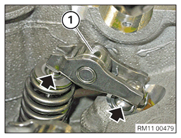
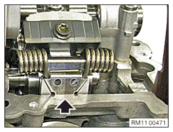
- Make sure that the roller cam follower (1) is correctly positioned on the hydraulic valve clearance compensating element (arrows) and the intake valves.
- Install the roller cam follower (1) on the exhaust side.
- Make sure that the roller cam follower (1) is positioned correctly on the hydraulic valve clearance compensating elements (arrows) and the exhaust valves.
Install exhaust camshaft
Further information is available.
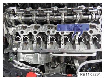
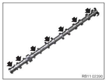
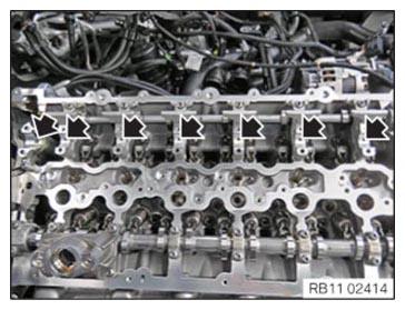
- Clean all the bearing positions (arrows).
- Coat all bearing positions (arrows) with motor oil.
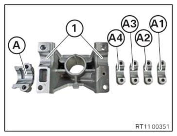
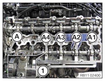
- Clean all bearing positions of the exhaust camshaft bearing caps (A1), (A2), (A3), (A4) and (A) and coat with motor oil.
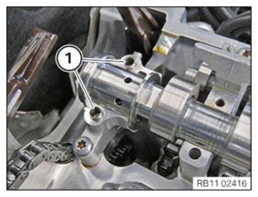
- Clean the bearing positions (1) of the high pressure pump bracket and coat with motor oil.
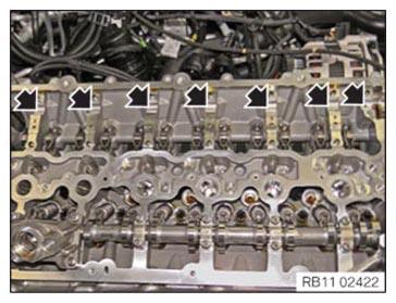
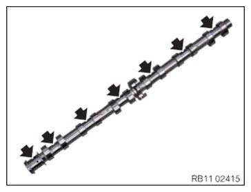
- Clean all the bearing positions (arrows) of the exhaust camshaft.
- Coat all bearing positions (arrows) of the exhaust camshaft with motor oil.
- Check all roller cam follower (1) of the exhaust side for correct fit.
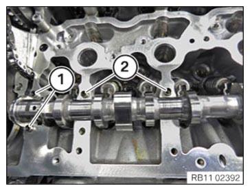
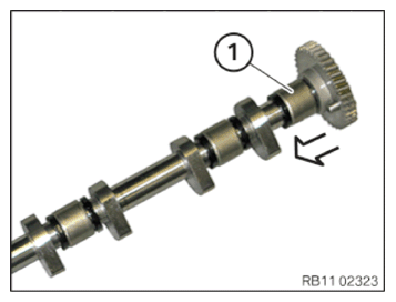
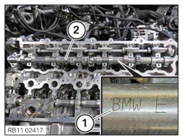
- Insert the exhaust camshaft (2) in the cylinder head, so that the mark (1) points upwards.
- Check the fitting sleeves (1) of the thrust bearing for damage, replace if necessary.
- Check the fitting sleeves (2) of the high pressure pump bracket for damage, replace if necessary.NOTE: RISK OF DAMAGE
Engine damage caused by incorrectly installed bearing shells and bearing brackets.
If the bearing shells and bearing brackets are installed incorrectly, then engine damage can occur.- Always install all bearing shells and bearing brackets in the same position from which they were removed.
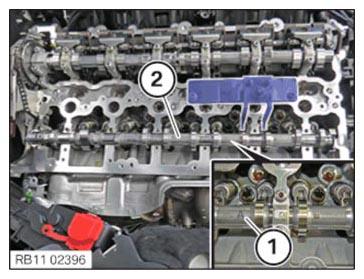
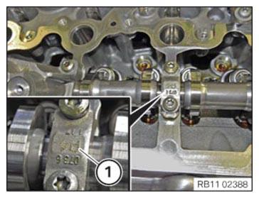
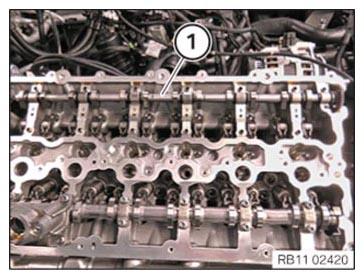
- Replace all exhaust camshaft bearing cap so that the labeling (1) from the intake side are readable.NOTE: TECHNICAL INFORMATION
The camshaft bearing caps must not be mixed up. The camshaft bearing caps must be installed in the installation position from which they were removed. - Oil all the exhaust camshaft bearing caps (A1) to (A4) and the exhaust camshaft bearing cap for the thrust bearing (A) with motor oil and place into position.
- Oil the bearing position at the high pressure pump bracket with motor oil and place the high pressure pump bracket into position.
- Check the tensile strength of the screws for the bearing caps.
The illustration shows the screw with a tensile strength of 8.8.
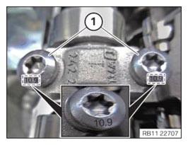
- Check the tensile strength of the screws for the bearing cap.
The illustration shows the screw with a tensile strength of 10.9.
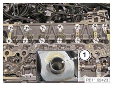
NOTE: TECHNICAL INFORMATION
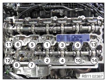
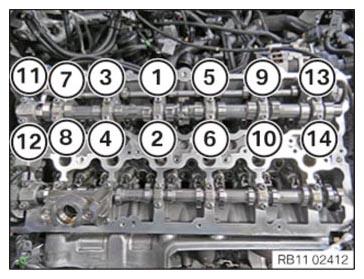
The camshaft is under tension due to the valve springs. Tighten or loosen each screw on the camshaft bearing caps in the prescribed sequence only by half a turn. Repeat procedure. - Press the exhaust camshaft bearing cap down and hand-tighten the screws incrementally in sequence (1) to (14).
- Abut all screws in the sequence from (1) to (14) in half turns.
- Observe the joining torque.
- Tighten
all screws in a sequence from (1) to (14).TIGHTENING TORQUES SPECIFICATION
Exhaust camshaft to cylinder head M6
Tensile strength of screw 8.8Joining torque 9.6 Nm Tightening torque 9.6 Nm M6
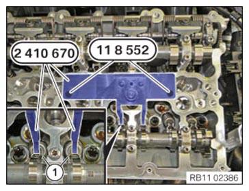
Tensile strength of screw 10.9Joining torque 11.8 Nm Tightening torque 11.8 Nm - Relax special tool 2 410 670 above the spindle nut.
- Release special tools 0 495 741 (11 8 552)
and remove the special tool 2 410 670.
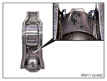
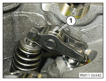
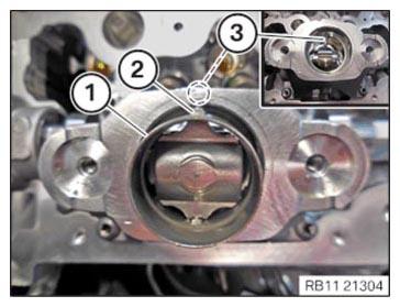
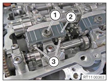
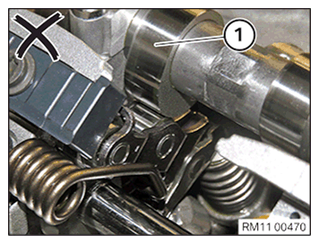
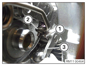
- Position and install the roller tappet (1).
- Make sure the pin (2) is correctly positioned in the guide (3).
- Insert and install the roller tappet (1).

Install eccentric shaft
Further information is available.
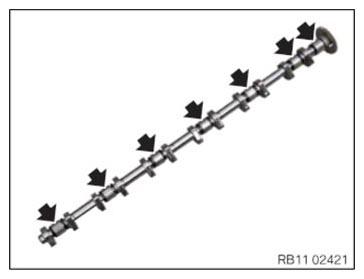
- Check all needle bearings (arrows) of the eccentric shaft for ease of movement.
- If the needle bearings are stiff, replace the eccentric shaft.
- Clean all bearing positions in cylinder head and coat with motor oil.
- Clean bearing positions (1) of the bearing brackets and coat with motor oil.
- Clean the bearing position (2) of the bearing cap and coat with motor oil.
- Check all guide bushings (1) for damage and replace faulty guide bushings (1).
- Slide the needle bearing (1) up to the stop in the arrow direction before installing the eccentric shaft.
- Oil all needle bearings of the eccentric shaft (1).
- Insert eccentric shaft (1) into the cylinder head.NOTE: RISK OF DAMAGE
Engine damage caused by incorrectly installed bearing shells and bearing brackets.
If the bearing shells and bearing brackets are installed incorrectly, then engine damage can occur. - Always install all bearing shells and bearing brackets in the same position from which they were removed.
- Install the bearing bracket.
All bearing brackets must be installed again in the same position from where they were removed.
- Tighten down screws (1).TIGHTENING TORQUES SPECIFICATION
Eccentric shaft to bearing bracket/cylinder head M6 Tightening torque 10 Nm - Install it with a bearing cap provided with a stop (1).
- Tighten down screws (1).TIGHTENING TORQUES SPECIFICATION
Eccentric shaft to bearing bracket/cylinder head M6 Tightening torque 10 Nm Installing servomotor for the eccentric shaft
Further information is available.
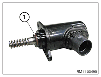
- Replace seal (1).
Parts: Gasket
- Press the seal (1) up to the limit position on the housing.
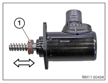
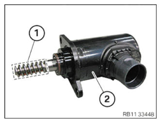
- Grease the gearing (1) of the servomotor for eccentric shaft (2) in the marked
area.
Parts: lubricating. grease
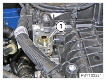
CONSUMABLE - LUBRICATING GREASE DESCRIPTIONLubricating grease Longtime PD-1 400 g, Cartridge 83192160340 - Clean sealing surface (1).
- Insert servomotor (1) till the gearing is lined up.
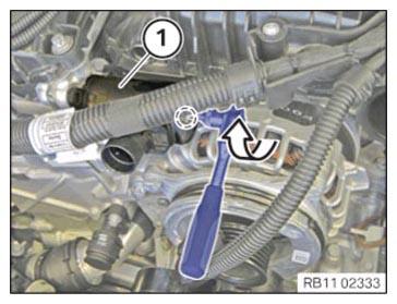
- Turn the servomotor (1) in the marked area to the right with conventional tools until it rests against the cylinder head.
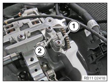
- Tighten down screws (1).TIGHTENING TORQUES SPECIFICATION
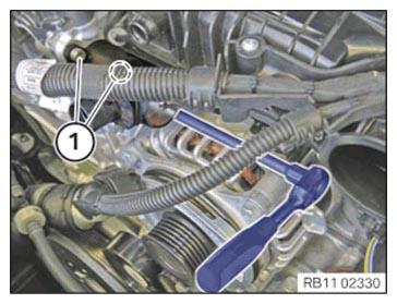
Servomotor for the eccentric shaft to cylinder head M6 x 16 Tightening torque 8 Nm - Lock connector (2).
- Position the ventilation line (1) on the intake plenum and lock.
Install intake camshaft
Further information is available.
- Clean all bearing positions and coat with motor oil.
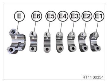
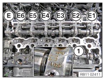
- Clean all bearing positions of intake camshaft bearing caps (E1) (E2) (E3), (E4) (E5) (E6) and (E) coat with motor oil.
- Clean all bearing positions of the intake camshaft and coat with motor oil.
- Check all the roller cam followers (1) of the intake side for correct fit.
- Insert intake camshaft (2) in the bearing brackets in such a way that the mark (1) points towards the top.
- Check fitting sleeves (1) of the thrust bearing for damage, replace if necessary.
Engine damage caused by incorrectly installed bearing shells and bearing brackets.
If the bearing shells and bearing brackets are installed incorrectly, then engine damage can occur.
- Always install all bearing shells and bearing brackets in the same position from which they were removed.
- Coat all the intake camshaft bearing caps (E1) till (E6) and lay the bearing caps for the thrust bearing (E) with motor oil.
- Check the tensile strength of the screws for the bearing cap.
The illustration shows the screw with a tensile strength of 8.8.
- Check the tensile strength of the screws for the bearing cap.
The illustration shows the screw with a tensile strength of 10.9.
NOTE: TECHNICAL INFORMATION
The camshaft is under tension due to the valve springs. Tighten or loosen each screw on the camshaft bearing caps in the prescribed sequence only by half a turn. Repeat procedure. - Press down the intake camshaft bearing cap and step wise apply the screws in the order of (1) to (14) until hand-tight.
- Join all bolts in sequence (1) to (14) in half turns.
- Observe the joining torque.
- Tighten
all screws in a sequence from (1) to (14).TIGHTENING TORQUES SPECIFICATION
Intake camshaft to cylinder head M6
Tensile strength of screw 8.8Joining torque 9.6 Nm Tightening torque 9.6 Nm M6
Tensile strength of screw 10.9Joining torque 11.8 Nm Tightening torque 11.8 Nm Checking installation position of roller cam followers
Further information is available.
NOTE: TECHNICAL INFORMATION
The rocker arms may slip slightly when the camshaft is positioned. Make sure rocker arms are correctly positioned on the hydraulic valve clearance compensating elements and on valves. - Check rocker arm for correct installation position.
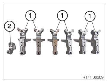
Checking the intermediate lever classification
Further information is available.
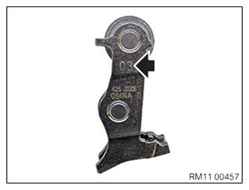
NOTE: TECHNICAL INFORMATION
All intermediate levers are classified. Only one classification may be used per engine.
All intermediate levers must be reinstalled in the same positions in an engine which has already been in use. - Check the classification (arrow) of the intermediate lever.
Installing all intermediate levers
Further information is available.
NOTE: TECHNICAL INFORMATION
When replacing one or more intermediate levers:
When removing the intermediate lever, it is imperative to note the part number of the intermediate lever.
A mixed installation of intermediate levers is only permitted in combination with the appropriate torsion spring.
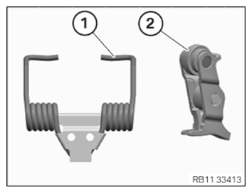
For further information on possible combinations, see the applicable BMW parts catalogue. - Version with a torsion spring with an L-shaped contour and a suitable intermediate lever:
Use a torsion spring (1) with L-shaped contour only in connection with the suitable intermediate lever (2).
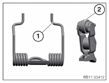
- Version with a torsion spring with an S-shaped contour and a suitable intermediate lever:
Use a torsion spring (1) with the s-shaped contour only in connection with the suitable intermediate lever (2).
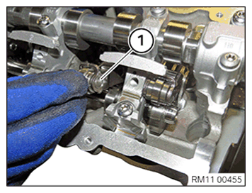
NOTE: The description is for one component only. The procedure is identical for all further components. - Install the intermediate lever (1).
Installing all gates
Further information is available.
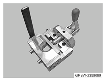
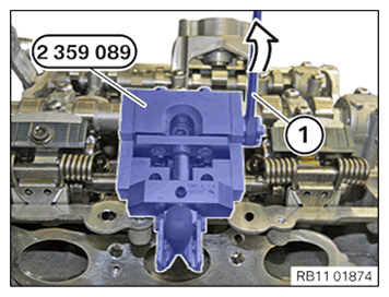
- Have the special tool 2 359 089
ready.
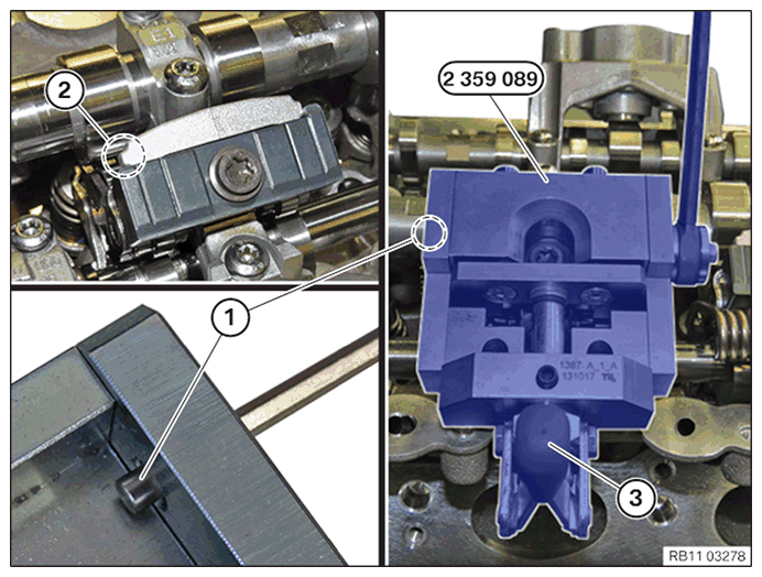
- Clean contact surfaces (1) and (2) off oil, grease and dirt.
- Fit the gate (2) and hand-tighten the screw (1).
- Make sure the intermediate lever (3) is in the correct installation position.
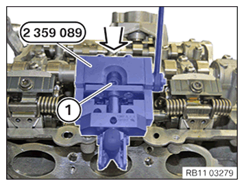
- Position the special tool 2 359 089 on the cylinder head.
- Pre-tension the gate with the lever (3).
- Bring the screw (1) onto the contact surface in the area (2).
- Make sure that the special tool 2 359 089
does not rotate during this process.
- Attach the gate with the lever (1) in arrow direction.
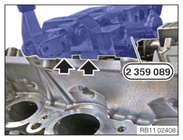
- Make sure that the special tool 2 359 089
rests flat against the cylinder head (arrows).
- Press the special tool 2 359 089
in arrow direction onto the cylinder head. Simultaneously tighten the screw (1).TIGHTENING TORQUES SPECIFICATION
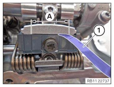
Gate to bearing bracket M7 Tightening torque 20 Nm - Check the conventional gauge (1) in the area (A) for the correct gap dimension.TECHNICAL DATA - GAP DIMENSION SPECIFICATION
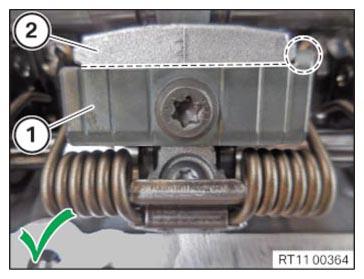
Gap dimension between gate and bearing bracket Gap dimension A 0.03 mm - Make sure that the gate (1) lies correctly on the bearing bracket (2).
The gate (1) is installed correctly in the marked area.
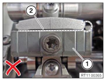
- Make sure that the gate (1) lies correctly on the bearing bracket (2).
The gate (1) is not installed correctly in the marked area.
- Repeat the process for all gates.
Checking the position of the intake camshaft (cylinder head removed)
Check
- Check position of the intake camshaft on the respective cylinders.
Result
» Cam (1) of the intake camshaft runs on the intermediate lever.
Measure
- Continue to crank the intake camshaft on the mounting flats.
Checking the position of the intake camshaft at cylinders 3 and 4 (cylinder head removed)
Check
- Check the position of the intake camshaft at cylinder 3 and 4.
To remove the torsion springs on cylinders 3 and 4, the camshaft sensor wheel (1) of the intake camshaft must be in the position shown.
Result
» The camshaft sensor wheel (1) of the intake camshaft is not in the position shown.
Measure
- Continue to crank the intake camshaft on the mounting flats.
Installing torsion springs
Further information is available.
Injury hazard!
- The use of the specified special tool (tool) is mandatory.
- Carry out the described steps properly.
Wear safety goggles.
For disassembly and installation of the torsion spring, special tool 2 359 088 is used. Due to technical modifications in the torsion spring, special tool 5 A0B 120 is mounted on the existing special tool 2 359 088.
Information on modification can be found in the additional information.
Alternative to the new special tool 5 A24 F30, the already known special tool SWZ: 2 359 088 can be used in modified form.
Information on modification can be found in the additional information.
The modified special tool is upward compatible.
When replacing one or more torsion springs:
When removing the torsion spring, it is imperative to note the part number of the torsion spring.
A mixed installation of torsion springs is only permitted in combination with the appropriate intermediate lever.
For further information on possible combinations, see the applicable BMW parts catalogue.
- Version with a torsion spring with an L-shaped contour and a suitable intermediate lever:
Use torsion spring (1) with an L-shaped contour only in conjunction with a suitable intermediate lever (2).
- Version with a torsion spring with an S-shaped contour and a suitable intermediate lever:
Use torsion spring (1) with an S-shaped contour only in conjunction with a suitable intermediate lever (2).
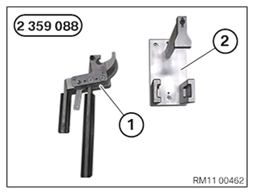
- Keep set of special tools 2 359 088
for removing the torsion spring with an S-shaped contour ready:
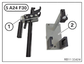
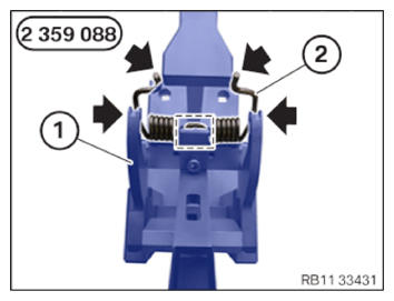
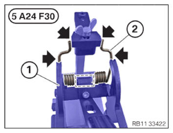
Number Description 1 Clamping lever 2 Mount for the clamping lever (torsion spring with an S-shaped contour) - Keep set of special tools 5 A24 F30
or, alternatively, the modified special tool 2 359 088
for removing the torsion spring with an L/S-shaped contour ready:
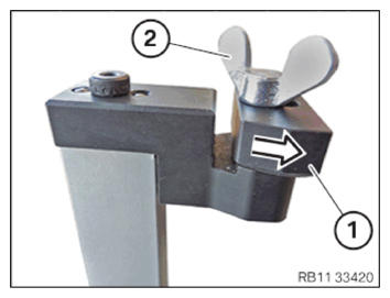
Number Description 1 Clamping lever 2 Mount for the clamping lever (torsion spring with an L/S-shaped contour) - Version with a torsion spring with an S-shaped contour with special tool 5 A24 F30 or the modified special tool 2 359 088:
Move shaped part (1) to the contact surface in the arrow direction.
Turn wing screw (2) until hand-tight.
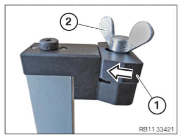
- Version with a torsion spring with an L-shaped contour with special tool 5 A24 F30 or the modified special tool 2 359 088:
Move shaped part (1) to the contact surface in the arrow direction.
Turn wing screw (2) until hand-tight.
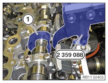
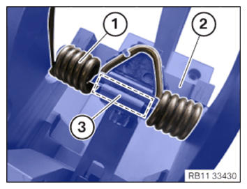
- Position torsion spring (1) in clamping lever (2).
Torsion spring (1) must be positioned correctly in the marked area (3) of clamping lever (2).
- Version with a torsion spring with an S-shaped contour with special tool 2 359 088:
Close clamping lever (1) of special tool 2 359 088 carefully in the corresponding mount until the snap-in hooks engage audibly.
Ensure that torsion spring (2) lies correctly in the lateral guides (arrows) and mark of clamping lever (1) when tensioning.
- Version with a torsion spring with an S-shaped contour with special tool 5 A24 F30 or the modified special tool 2 359 088:
Close clamping lever (1) of special tool 5 A24 F30 or the modified special tool 2 359 088 carefully in the corresponding mount until the snap-in hooks engage audibly.
Ensure that torsion spring (2) lies correctly in the lateral guides (arrows) and mark of clamping lever (1) when tensioning.
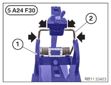
- Version with a torsion spring with an L-shaped contour with special tool 5 A24 F30 or the modified special tool 2 359 088:
- Close clamping lever (1) of special tool 5 A24 F30 or the modified special tool 2 359 088 carefully in the corresponding mount until the snap-in hooks engage audibly.
- Ensure that torsion spring (2) lies correctly
in the lateral guides (arrows) and mark
of clamping lever (1) when tensioning.
- Move clamping lever (2) with the tensioned torsion spring carefully
out of mount (3) in the arrow direction.
- Insert torsion spring (2) with clamping lever (1) into cylinder head (3).
- Version with a torsion spring with an S-shaped contour on an intermediate lever
- Insert the torsion spring (2) into the intermediate levers (1).
- Check all roller cam followers (3) for correct installation position.
- Place clamping lever (1) flat in the marked area (2).
- Press together clamping lever (1) until snap-in hooks (3) unlock audibly.
- Open clamping lever (1) carefully until the torsion spring is fully relaxed.
- Guide out and remove clamping lever (1).
- Fit torsion spring (1) correctly
in the arrow direction using a standard plastic hammer (3) and a standard plastic wedge (2).
- Check the correct installation position of the torsion spring (arrow).
Follow-up work