Installing the oil coolant heat exchanger
NOTE:
RISK OF DAMAGE
Damage to the surface.
The use of metal-cutting tools (e.g., emery cloths) for cleaning surfaces can damage them and lead to leaks and/or engine damage.
Damage to the surface.
The use of metal-cutting tools (e.g., emery cloths) for cleaning surfaces can damage them and lead to leaks and/or engine damage.
- Do not use any metal-cutting tools.
NOTE:
TECHNICAL INFORMATION
The sealing surfaces must be free of oil, grease and cleaning agents.
The sealing surfaces must be free of oil, grease and cleaning agents.
NOTE:
TECHNICAL INFORMATION
Clean all threaded belt connections with micro-encapsulated outer and internal threads.
Shavings or other debris must not remain in the components.
If a microencapsulated screw is reused, it must be coated with the following screw locking agent: Loctite 243, medium strength.
The screw connection must be completed within 10 minutes as hardening begins after this period.
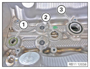
- Clean and recut the threads in the engine block.
- Replace sealing ring (1).
Parts : Sealing ring
- Replace sealing ring (2).
Parts : Sealing ring
- Replace sealing ring (3).
Parts : Sealing ring
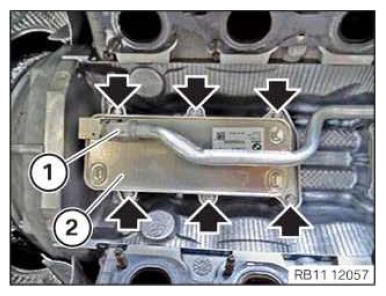
- Replace the bolts (arrows).
Parts : Screws
- Position the oil coolant heat exchanger (2) and tighter the screws (arrows).TIGHTENING TORQUES SPECIFICATION
Oil-coolant heat exchanger on crankcase M6x14 screw
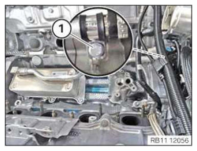
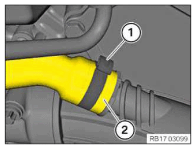
Replace screwstightening torque 12 Nm - Connect and lock the coolant tube (1).
The coolant tube (1) must engage audibly.
- Tighten down screw (1).TIGHTENING TORQUES SPECIFICATION
Coolant line to cylinder head M6 tightening torque 8 Nm NOTE: TECHNICAL INFORMATION
For contamination of the cooling system (e.g. by motor oil), the cooling system must be rinsed with water until all contamination is removed.NOTE: To provide a better overview: Illustration of surrounding parts removed. - Version B:
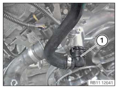
Connect the coolant return line (1) to the auxiliary coolant pump and lock It audibly.
- Version B:
Position the coolant hose (2).
Ranew circlip (1).
Tighten clamp (1),
Follow-up work
- Refer to INSTALLING LOWER HEAT SHIELD .
- Refer to INSTALLING BOTH EXHAUST MANIFOLDS .
- Refer to INSTALLING FRONT HEAT SHIELD .
- Refer to INSTALLING ALTERNATOR .
- Refer to INSTALLING BOTH EXHAUST TURBOCHARGERS .
- Refer to ATTACHING THE CHARGE AIR COOLER .
- Refer to INSTALLING THE CLEAN AIR PIPE OF CYLINDER BANK 2 .
- Refer to CONNECTING THE LEFT CHARGE AIR LINE TO THE EXHAUST TURBOCHARGER .
- Refer to INSTALLING CLEAN AIR PIPE OF CYLINDER BANK 1 .
- Refer to CONNECTING THE RIGHT CHARGE AIR LINE TO THE EXHAUST TURBOCHARGER .
- Refer to CLOSING THE HIGH-TEMPERATURE COOLANT CIRCUIT .
- Refer to INSTALLING THE UNDERBODY PROTECTION OF THE STEERING GEAR OR THE FRONT THRUST FIELD .
- Refer to INSTALLING THE FRONT UNDERBODY PROTECTION OR FRONT THRUST FIELD .
- Refer to INSTALLING THE FRONT LEFT BOTTOM WHEEL ARCH COVER .
- Refer to INSTALLING THE FRONT BOTTOM RIGHT WHEEL ARCH COVER .
- Refer to INSTALLING DRIVE BELT .
- Refer to PARTIALLY FASTENING THE COOLANT EXPANSION TANK FOR THE LOW-TEMPERATURE COOLANT CIRCUIT .
- Refer to INSTALLING FAN COWL .
- Refer to INSTALLING THE REAR TOP CROSS CONNECTION .
- Refer to INSTALLING FRONT CROSS CONNECTION .
- Refer to INSTALLING THE RIGHT INTAKE FILTER HOUSING WITH THE RIGHT FRONT-END STRUT .
- Refer to INSTALLING LEFT INTAKE FILTER HOUSING WITH LEFT FRONT-END STRUT .
- Refer to INSTALLING THE COVER ON THE LEFT AND RIGHT IN THE ENGINE COMPARTMENT AT THE TOP .
- Refer to INSTALLING THE CATALYTIC CONVERTER FOR CYLINDERS 5 TO 8 .
- Refer to RELEASING THE HEAT SHIELD .
- Refer to INSTALLING THE CENTER COWL UPPER PART .
- Refer to INSTALLING TENSION STRUT ON SHOCK TOWER .
- Refer to INSTALLING WINDSHIELD PANEL COVER .
- Refer to INSTALLING LEFT AND RIGHT WIPER ARM .
- Refer to INSTALLING THE REAR RIGHT ENGINE COMPARTMENT COVER .
- Refer to INSTALLING THE COVER OF THE ENGINE COMPARTMENT ON THE REAR LEFT .
- Refer to INSTALLING RIGHT HEAT SHIELD .
- Refer to INSTALLING LEFT HEAT SHIELD .
- Refer to INSTALLING HEAT SHIELD, TOP .
- Refer to INSTALLING THE RIGHT OXYGEN SENSOR MONITOR .
- Refer to INSTALLING THE LEFT OXYGEN SENSOR MONITOR .
- Refer to PARTIALLY INSTALLING THE RIGHT LAMBDA OXYGEN SENSOR .
- Refer to PARTIALLY INSTALLING THE LEFT LAMBDA OXYGEN SENSOR .
- Refer to INSTALLING THE RETAINING BRIDGE .
- Refer to INSTALLING EXHAUST SYSTEM .
- Refer to INSTALLING CENTER REAR UNDERSHIELD .
- Refer to INSTALLING THE CONNECTING SUPPORTS ON THE TUNNEL .
- Refer to CONNECTING NEGATIVE BATTERY CABLE .
- Refer to FILLING AND VENTING THE HIGH-TEMPERATURE COOLANT CIRCUIT .
- Refer to CHECKING ENGINE OIL LEVEL .