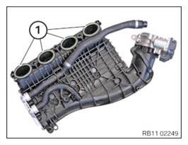
Installing the intake plenum
- Replace gaskets (1).
Parts: Seals
NOTE: TECHNICAL INFORMATION
Additional coolant can leakage. Make sure that no coolant enters the intake port of the cylinder head. - Position the intake plenum at the cylinder head.
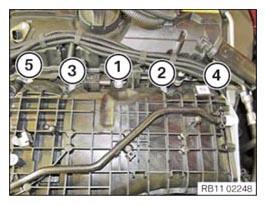
- Tighten screws in the order (1) to (5).NOTE: Tighten the bolts in 360 degree steps.TIGHTENING TORQUES SPECIFICATION
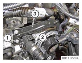
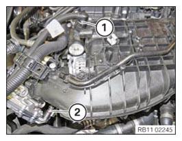
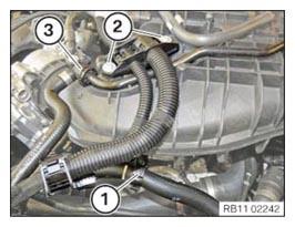
Intake plenum to cylinder head M6 Tightening torque 10 Nm - Position holder (3).
- Attach the coolant feed line (2) to the clamp.
- Tighten the screws (1).TIGHTENING TORQUES SPECIFICATION
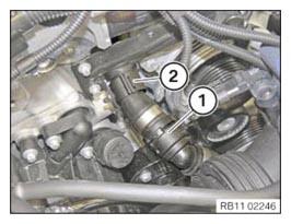
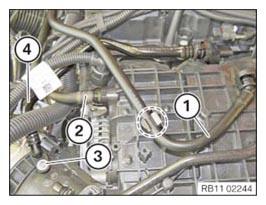
Holder for intake system to cylinder head/crankcase M6 Tightening torque 10 Nm - Tighten the screws (1).TIGHTENING TORQUES SPECIFICATION
Intake system to holder front/rear Tightening torque 8 Nm NOTE: TECHNICAL INFORMATION
Make sure that the connections are locked correctly. The locks must engage audibly. - Lock clamp (2).
- Connect the coolant feed line (1).
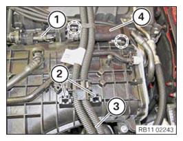
- Correctly route the wiring harness and connect the connectors (1) and (2).
- Position the ventilation line (4) and tighten the bolt (3).TIGHTENING TORQUES SPECIFICATION
Tank vent line to intake system Tightening torque 5 Nm NOTE: TECHNICAL INFORMATION
Detents, guides and mounting elements must not be damaged or missing. - Connect the ventilation line (2).
- Clip the ventilation line (1) in at the marked area.
- Attach the ventilation line (4) in the marked area.
- Position the wiring harness (3) and clip it in to the holder (2).
- Clip in engine wiring harness in the marked area.
- Connect connector (1).
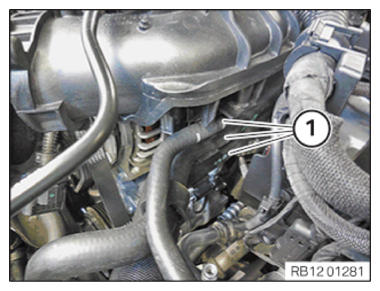
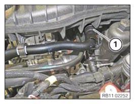
- Attach the coolant lines (1).NOTE: TECHNICAL INFORMATION
Make sure that the connections are locked correctly. The locks must engage audibly. - Lock and connect the coolant line (3).
- Correctly route the engine wiring harness and tighten it with the bolts (2).TIGHTENING TORQUES SPECIFICATION
Holder for wiring harness to intake system screw Tightening torque 5 Nm - Clip the coolant return line into the clamp (1).NOTE: TECHNICAL INFORMATION
Make sure that the connections are locked correctly. The locks must engage audibly. - Lock and connect the coolant return line (1).

Follow-up work
- Refer to INSTALLING CONTROL UNIT BRACKET .
- Refer to INSTALLING THE DME CONTROL UNIT .
- Refer to INSTALLING THE TANK VENTING VALVE .
- Refer to INSTALLING ACOUSTIC COVER AT REAR .
- Refer to INSTALLING THE FRONT HOOD SEAL AT THE REAR .
- Refer to INSTALLING THE ACOUSTIC COVER FOR THE ENGINE AT THE FRONT .
- Refer to INSTALLING CHARGE AIR LINE .
- Refer to CONNECTING THE COOLANT LINE OF LOW-TEMPERATURE COOLANT CIRCUIT .
- Refer to FILLING THE LOW-TEMPERATURE COOLING SYSTEM WITH THE VACUUM FILLING EQUIPMENT .
- Refer to INSTALLING CLEAN AIR PIPE .
- Refer to INSTALLING RESONATOR .
- Refer to INSTALLING ACOUSTIC COVER .
- Refer to VENTING THE LOW-TEMPERATURE COOLING SYSTEM .
- Refer to INSTALLING THE UNDERBODY PROTECTION OF THE STEERING GEAR OR THE FRONT THRUST FIELD .
- Refer to INSTALLING THE FRONT UNDERBODY PROTECTION OR FRONT THRUST FIELD .