Checking camshaft timing (AT)
WARNING:
Hot surfaces.
Risk of burning!
Risk of burning!
- Perform all work only on components that have cooled down.
NOTE:
TECHNICAL INFORMATION
Collect and dispose of emerging fluids. Observe country-specific waste disposal regulations.
Collect and dispose of emerging fluids. Observe country-specific waste disposal regulations.
Preliminary work
- Refer to DISCONNECTING ALL BATTERY GROUND LEADS .
- Refer to REMOVING THE ACOUSTIC COVER .
- Refer to REMOVING INTAKE SILENCER HOUSING .
- Refer to REMOVING THE RESONATOR WITH THE TOP CLEAN AIR PIPE .
- Refer to REMOVING THE COVER ON LEFT AND RIGHT IN THE ENGINE COMPARTMENT AT THE TOP .
- Refer to REMOVING THE LEFT AND RIGHT FRONT-END STRUT .
- Refer to REMOVING FRONT CROSS CONNECTION .
- Refer to REMOVING THE REAR TOP CROSS CONNECTION .
- Refer to REMOVING THE FAN COWL .
- Refer to REMOVING THE SEAL FOR THE HOOD REAR .
- Refer to REMOVING ACOUSTIC COVER AT REAR .
- Refer to REMOVING THE COVER OF THE ENGINE COMPARTMENT AT THE REAR LEFT .
- Refer to REMOVING LEFT AND RIGHT WIPER ARM .
- Refer to REMOVING THE COWL COVER .
- Refer to REMOVING TRAILING LINK AT SPRING BOLT .
- Refer to REMOVING THE COWL UPPER PART IN THE CENTER .
- Refer to REMOVING THE SEALING FRAME ON LEFT AND RIGHT .
- Refer to REMOVING THE CENTER BULKHEAD LOWER PART .
- Refer to REMOVING BOTH ACTUATORS .
- Refer to REMOVING FRONT ENGINE ENCAPSULATION .
- Refer to REMOVING IGNITION COILS .
- Refer to REMOVING THE HIGH PRESSURE LINE BETWEEN THE RAIL AND THE HIGH PRESSURE PUMP .
- Refer to REMOVING HIGH PRESSURE PUMP .
- Refer to REMOVING THE INJECTORS FOR CYLINDERS 1 TO 3 .
- Refer to REMOVING THE INJECTORS FOR CYLINDERS 4 TO 6 .
- Refer to REMOVING THE CYLINDER HEAD COVER .
- Refer to REMOVING THE FRONT UNDERBODY PROTECTION OR FRONT THRUST FIELD .
- Refer to REMOVING THE UNDERBODY PROTECTION OF THE STEERING GEAR AND THRUST FIELD RESPECTIVELY .
- Refer to REMOVING THE STIFFENING PLATE .
- Refer to REMOVING STARTER MOTOR .
NOTE:
RISK OF DAMAGE
Damage to the engine.
If the engine is manually rotated in the wrong direction of rotation, the engine can be damaged.
Damage to the engine.
If the engine is manually rotated in the wrong direction of rotation, the engine can be damaged.
- Only rotate the engine manually in the correct direction of rotation: a) clockwise when looking at the damper, or b) counterclockwise when looking at the chain drive. b) applies only if the timing chain is installed in the rear.
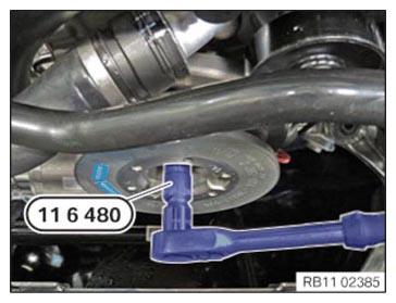
- With the special tool, turn the engine 0 493 380 (11 6 480)
to the TDC firing position of cylinder 1.
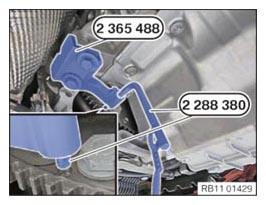
Blocking the crankshaft in the TDC firing position of the first cylinder (automatic transmission)
- Version with automatic transmission:
- Position the special tool 2 365 488
and secure with the corresponding screws.
Block the crankshaft with the special tool 2 288 380 in the TDC firing position of the first cylinder.
Check
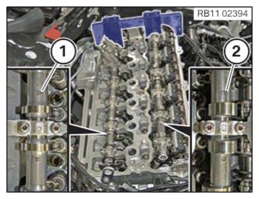
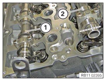
- Check whether the mark (1) of the exhaust camshaft and the mark (2) of the intake camshaft can be read from above.
Result
» Marks (1) and (2) cannot be read from the top.
Measure
- Turn the camshafts to the correct position or readjust the valve timing.
Check
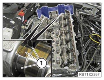
- Check whether the center of the three flattened areas (1) on both camshafts points upwards. The special tool 2 358 122 can also be mounted if the camshafts are twisted by 180° (central flattened area points downwards).
Result
» The center of the three flattened areas (1) does not point upwards.
Measure
- Turn the camshafts to the correct position such that the center of the three flattened areas (1) on both camshafts points upwards.
- Check whether the cam of the exhaust camshaft (1) and the intake camshaft (2) are positioned on cylinder 1 as shown.
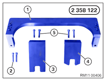
- Keep set of special tools 2 358 122
at hand:
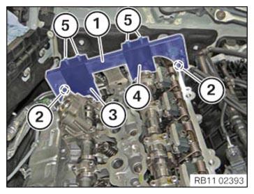
Number Description 1 Basic carrier 2 Basic carrier screws on cylinder head 3 Gauge to fix exhaust camshaft 4 Gauge to fix intake camshaft 5 Screw gauge on basic carrier - Secure the basic carrier (1) of the special tool 2 358 122 with the screws (2) the cylinder head.
- Position gauge (3) with the recess on the exhaust camshaft and fix with the screws (5) on the basic carrier (1).
- Position gauge (4) with the recess on the intake camshaft and fix with the screws (5) on the basic carrier (1).NOTE: If the special tool 2 358 122 cannot be mounted, the valve timing must readjusted.
Follow-up work
- Refer to DISASSEMBLING THE SPECIAL TOOL 2 358 122 .
- Refer to DISASSEMBLING THE SPECIAL TOOL 2 288 380 .
- Refer to INSTALLING STARTER MOTOR .
- Refer to INSTALLING CYLINDER HEAD COVER .
- Refer to PREPARING THE INJECTORS FOR INSTALLATION .
- Refer to INSTALLING THE INJECTORS FOR THE CYLINDERS 4 TO 6 .
- Refer to INSTALLING THE INJECTORS FOR THE CYLINDERS 1 TO 3 .
- Refer to PREPARING FOR THE INSTALLATION OF THE HIGH PRESSURE PUMP .
- Refer to INSTALLING HIGH PRESSURE PUMP .
- Refer to INSTALLING THE HIGH-PRESSURE LINE BETWEEN THE HIGH-PRESSURE RAIL AND THE HIGH-PRESSURE PUMP .
- Refer to INSTALLING THE IGNITION COILS .
- Refer to INSTALLING FRONT ENGINE ENCAPSULATION .
- Refer to INSTALLING BOTH ACTUATORS .
- Refer to INSTALLING CENTER BULKHEAD LOWER PART .
- Refer to INSTALLING THE SEALING FRAME ON LEFT AND RIGHT .
- Refer to INSTALLING THE CENTER COWL UPPER PART .
- Refer to INSTALLING TENSION STRUT ON SHOCK TOWER .
- Refer to INSTALLING WINDSHIELD PANEL COVER .
- Refer to INSTALLING LEFT AND RIGHT WIPER ARM .
- Refer to INSTALLING THE COVER OF THE ENGINE COMPARTMENT ON THE REAR LEFT .
- Refer to INSTALLING ACOUSTIC COVER AT REAR .
- Refer to INSTALLING THE FRONT HOOD SEAL AT THE REAR .
- Refer to INSTALLING FAN COWL .
- Refer to INSTALLING THE REAR TOP CROSS CONNECTION .
- Refer to INSTALLING FRONT CROSS CONNECTION .
- Refer to INSTALLING FRONT-END STRUT ON LEFT AND RIGHT .
- Refer to INSTALLING THE COVER ON THE LEFT AND RIGHT IN THE ENGINE COMPARTMENT AT THE TOP .
- Refer to INSTALLING THE RESONATOR WITH THE TOP CLEAN AIR PIPE .
- Refer to INSTALLING INTAKE SILENCER HOUSING .
- Refer to INSTALLING ACOUSTIC COVER .
- Refer to INSTALLING THE THRUST FIELD .
- Refer to INSTALLING THE UNDERBODY PROTECTION OF THE STEERING GEAR OR THE FRONT THRUST FIELD .
- Refer to INSTALLING THE FRONT UNDERBODY PROTECTION OR FRONT THRUST FIELD .
- Refer to CONNECTING NEGATIVE BATTERY CABLE .