Removing the engine wiring harness for sensor system 2
NOTE:
DANGER
High-voltage system.
The high-voltage system operates on the basis of hazardous, electrical voltage and high currents. Mortal hazard through electric shock!
High-voltage system.
The high-voltage system operates on the basis of hazardous, electrical voltage and high currents. Mortal hazard through electric shock!
- All work on the high-voltage system may only be carried out by specially trained and technically experienced personnel.
- For additional information see:
- For additional information see:
WARNING:
Hot surfaces.
Risk of burning!
Risk of burning!
- Perform all work only on components that have cooled down.
Preliminary work
- Refer to DISCONNECTING ALL BATTERY GROUND LEADS .
- Refer to BRINGING FRONT COMPARTMENT LID IN THE SERVICE POSITION .
- Refer to REMOVING THE ACOUSTIC COVER .
- Refer to REMOVING THE SEAL FOR THE HOOD REAR .
- Refer to REMOVING THE COVER OF THE ENGINE COMPARTMENT AT THE REAR LEFT .
- Refer to REMOVING THE COVER OF THE REAR RIGHT ENGINE COMPARTMENT .
- Refer to REMOVING LEFT AND RIGHT WIPER ARM .
- Refer to REMOVING THE COWL COVER .
- Refer to REMOVING TRAILING LINK AT SPRING BOLT .
- Refer to REMOVING THE CENTER COWL UPPER PART .
- Refer to LOOSENING HIGH-VOLTAGE CABLES ON THE ELECTRICAL MACHINE ELECTRONICS .
- Refer to REMOVING ACOUSTIC COVER AT REAR .
- Refer to REMOVING INTAKE SILENCER HOUSING .
- Refer to REMOVING RESONATOR .
- Refer to REMOVING CHARGE AIR LINE .
- Refer to REMOVING THE ACOUSTIC COVER FOR THE ENGINE AT THE FRONT .
- Refer to REMOVING ENGINE VENTILATION LINE .
- Refer to REMOVING THE DIFFERENTIAL PRESSURE SENSOR .
- Refer to REMOVING THE CYLINDER HEAD COVER ACOUSTIC COVER .
- Refer to UNINSTALL COVER FOR THE DME CONTROL UNIT .
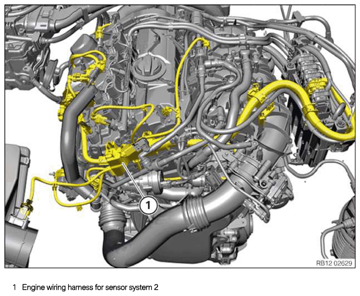
Engine wiring harness for sensor system 2
NOTE:
RISK OF DAMAGE
Electrostatic discharge.
Damage to or destruction of electrical components.
Electrostatic discharge.
Damage to or destruction of electrical components.
- Leave the electrical components in their original packaging until they are being installed. Only use the original packaging for returning the product. Always package removed components straight away.
- Read and comply with user information on using the associated special tool 12 7 060.
- Only tap the housings of electrical components. Do not tap pins or multi-pin connectors directly.
- Wear electrically conductive clothing and antistatic shoes (with ESD symbol).
- For additional information see: NOTES ON ESD (ELECTROSTATIC DISCHARGE) PROTECTION .
NOTE:
RISK OF DAMAGE
Damage to wires when disconnecting connectors and plug connections.
Sheared wires can cause a short circuit.
Damage to wires when disconnecting connectors and plug connections.
Sheared wires can cause a short circuit.
- Do not pull on wires when disconnecting connectors and plug connections.
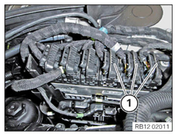
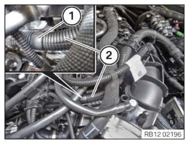
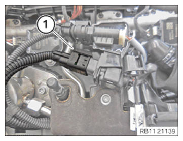
- Unlock and disconnect plug connections (1).
- Unlock plug connection (1) and disconnect.
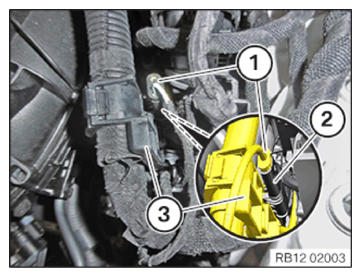
- Unlock the connector (2) and disconnect from the bracket (3).
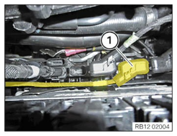
- Unlock plug connection (1) and disconnect.
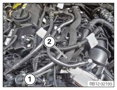
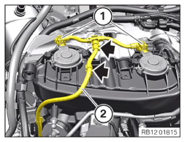
- Unlock the holder (1).
- Feed out coolant line (2) and place to one side.
- Unlock the holder (1).
- Feed out the wiring harness section (2) for the sensor system 2 and set it aside.
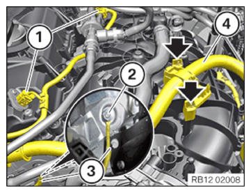
- Version A:
Unlock and disconnect plug connections (1).
Loosen nut (2).
Feed out the ground cable (3) and remove.
Unlock the locks (arrows), guide out wiring harness section (4) for sensor system 2 and keep it aside.
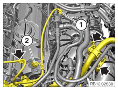
- Version B:
Unlock the locks and clamps (arrows).
Unlock and pull off connector (1) from the tank vent valve.
Unlock and pull off connector (2) from the intake camshaft sensor.
Guide out the wiring harness section for sensor system 2 and keep it aside.
- Loosen clamp (1).
- Unlock and disconnect plug connections (1).
- Release the clamps (arrows).
- Feed out the wiring harness section (2) for the sensor system 2 and set it aside.
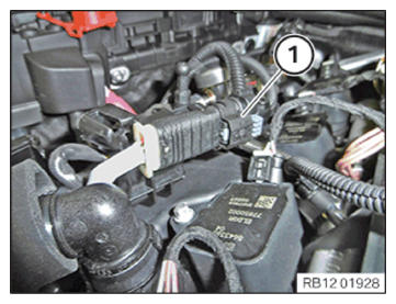
- Unlock plug connection (1) and disconnect.
- Unlock plug connection (1) (arrow) and disconnect from the holder (2).
Unlock plug connection (1) and disconnect.
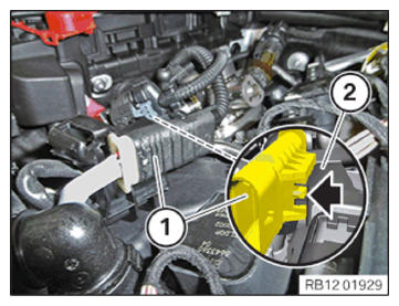
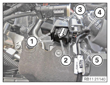
- Unlock the locks (1).
- Feed out the connector (2) from the holder (3) in the arrow direction and place to one side.
- Release the cable (4) from the clamp (5).
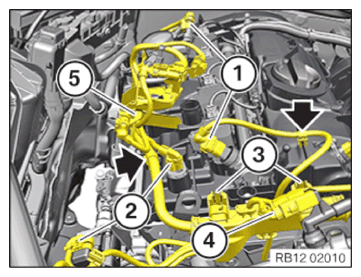
- Unlock and disconnect plug connections (1).
- Unlock and disconnect plug connections (2).
- Release the clamps (arrows).
- Unlock and loosen the locks (3).
- Unlock plug connection (4) and disconnect.
- Feed out the wiring harness section (5) for the sensor system 2 and set it aside.
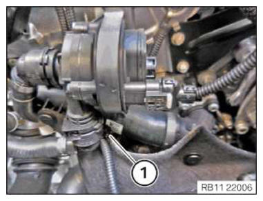
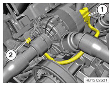
- Unlock connector (1) and unlock and detach it from the auxiliary coolant pump.
- Loosen clamp (2).
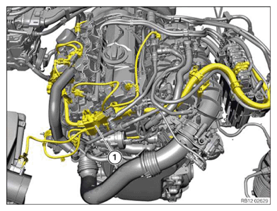
- Feed out and remove the engine wiring harness (1) for the sensor system 2.