Installing the engine wiring harness for the sensor system 1
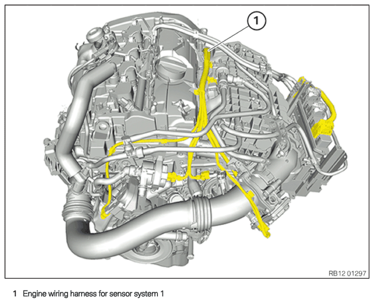
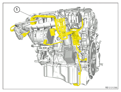
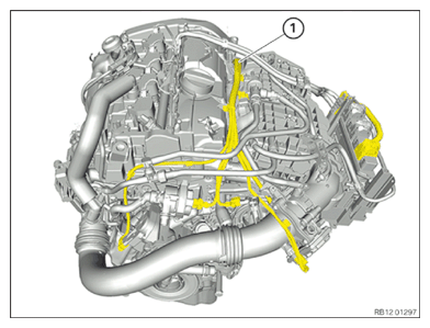
Engine wiring harness for sensor system 1
NOTE:
RISK OF DAMAGE
Improper routing of cables and wiring harnesses.
Trapped, crushed or damaged cables may cause short circuits and malfunctions.
Improper routing of cables and wiring harnesses.
Trapped, crushed or damaged cables may cause short circuits and malfunctions.
- Route all cables without abrasions, do not trap and crush.
- Insert and install the engine wiring harness for the sensor system 1 (1).
- Secure all clamps.
- Connect and lock the connector for the crankshaft sensor.
- Connect and lock the connector for the oil pressure switch.
- Connect and lock the connector for the solenoid valve.
- Connect and lock the connectors for the knock sensors.
- Connect and lock the connector for the coolant temperature sensor.
- Connect and lock the connector for the oil-level sensor.
The connectors must engage audibly.
- Connect and lock the connector for the alternator.
- Connect and lock the connector for the air conditioning compressor.
- Connect and lock the connector of the electric coolant pump.
- Connect and lock the connector for the heat management module.
- Connect and lock the connector of the boost pressure sensor.
- Connect and lock the connector for the throttle body.
- Connect and lock the connector for the charge-air temperature sensor.
The connectors must engage audibly.
Follow-up work
- Refer to INSTALLING THE INTAKE PLENUM .
- Refer to INSTALLING THE TANK VENT VALVE .
- Refer to INSTALLING CONTROL UNIT BRACKET .
- Refer to INSTALLING THE INTEGRATED POWER SUPPLY MODULE (PDM) .
- Refer to INSTALLING THE DME CONTROL UNIT .
- Refer to INSTALLING THE ACOUSTIC COVER FOR THE ENGINE AT THE FRONT .
- Refer to CONNECTING THE COOLANT LINES FOR THE LOW-TEMPERATURE COOLANT CIRCUIT .
- Refer to CONNECTING THE COOLANT LINE OF HIGH-TEMPERATURE COOLANT CIRCUIT .
- Refer to INSTALLING CHARGE AIR LINE .
- Refer to INSTALLING CLEAN AIR PIPE .
- Refer to INSTALLING RESONATOR .
- Refer to INSTALLING ACOUSTIC COVER AT REAR .
- Refer to INSTALLING THE FRONT HOOD SEAL AT THE REAR .
- Refer to FILLING THE LOW-TEMPERATURE COOLING SYSTEM WITH THE VACUUM FILLING EQUIPMENT .
- Refer to FILLING THE HIGH-TEMPERATURE COOLING SYSTEM WITH THE VACUUM FILLING EQUIPMENT .
- Refer to CONNECTING NEGATIVE BATTERY CABLE .
- Refer to VENTING THE LOW-TEMPERATURE COOLING SYSTEM .
- Refer to VENTING THE HIGH-TEMPERATURE COOLANT SYSTEM .
- Refer to CHECKING LOW-TEMPERATURE COOLING SYSTEM FOR WATERTIGHTNESS .
- Refer to CHECKING THE HIGH-TEMPERATURE COOLING SYSTEM FOR WATERTIGHTNESS .
- Refer to INSTALLING ACOUSTIC COVER .
- Refer to INSTALLING REAR UNDERBODY PROTECTION .
- Refer to INSTALLING THE UNDERBODY PLANKING OF THE TRANSMISSION ON THE SIDE .
- Refer to INSTALLING THE UNDERBODY PROTECTION OF THE STEERING GEAR OR THE FRONT THRUST FIELD .
- Refer to INSTALLING THE REAR THRUST FIELD .
- Refer to INSTALLING THE FRONT UNDERBODY PROTECTION OR FRONT THRUST FIELD .