Removing the wiring harness section of the transmission wiring harness
NOTE:
TECHNICAL INFORMATION
Additional coolant can leakage. Make sure that no coolant enters the intake port of the cylinder head.
Additional coolant can leakage. Make sure that no coolant enters the intake port of the cylinder head.
NOTE:
TECHNICAL INFORMATION
Collect and dispose of emerging fluids. Observe country-specific waste disposal regulations.
Collect and dispose of emerging fluids. Observe country-specific waste disposal regulations.
Preliminary work
- Refer to BRINGING FRONT COMPARTMENT LID IN THE SERVICE POSITION .
- Refer to REMOVING THE COVER OF THE ENGINE COMPARTMENT AT THE REAR LEFT .
- Refer to REMOVING THE COVER OF THE REAR RIGHT ENGINE COMPARTMENT .
- Refer to DEACTIVATING THE 48 V ELECTRICAL SYSTEM .
- Refer to DISCONNECTING ALL BATTERY GROUND LEADS .
- Refer to REMOVING THE SEAL FOR THE HOOD REAR .
- Refer to REMOVING LEFT AND RIGHT WIPER ARM .
- Refer to REMOVING THE COWL COVER .
- Refer to REMOVING TRAILING LINK AT SPRING BOLT .
- Refer to REMOVING THE COWL UPPER PART IN THE CENTER .
- Refer to REMOVING THE ACOUSTIC COVER .
- Refer to REMOVING ACOUSTIC COVER AT REAR .
- Refer to REMOVING THE DME CONTROL UNIT .
- Refer to REMOVING THE INTEGRATED POWER SUPPLY MODULE (PDM) .
- Refer to REMOVING THE CONTROL UNIT HOLDER .
- Refer to REMOVING THE COVER ON LEFT AND RIGHT IN THE ENGINE COMPARTMENT AT THE TOP .
- Refer to REMOVING BOTH FRONT-END STRUTS .
- Refer to REMOVING FRONT CROSS CONNECTION .
- Refer to REMOVING THE REAR TOP CROSS CONNECTION .
- Refer to REMOVING THE FAN COWL .
- Refer to REMOVING THE FRONT UNDERBODY PROTECTION OR FRONT THRUST FIELD .
- Refer to REMOVING THE UNDERBODY PROTECTION OF THE STEERING GEAR AND THRUST FIELD RESPECTIVELY .
- Refer to REMOVING THE STIFFENING PLATE .
- Refer to REMOVING REAR UNDERBODY PROTECTION .
- Refer to REMOVING THE CONNECTING SUPPORT FROM THE TUNNEL .
- Refer to IF INSTALLED: REMOVE THE TORSION STRUT ON THE RIGHT AND LEFT WHERE REQUIRED .
- Refer to REMOVING COMPLETE EXHAUST SYSTEM .
- Refer to REMOVING TRANSMISSION BEARING SUPPORT (ALL-WHEEL DRIVE VEHICLE) .
- Refer to REMOVING TRANSMISSION MOUNTING BRACKET (ALL-WHEEL DRIVE VEHICLE) .
- Refer to REMOVING THE HEAT SHIELDS .
- Refer to PARTIALLY LOOSENING THE PROP SHAFT .
- Refer to DRAINING THE COOLANT FROM THE LOW-TEMPERATURE COOLING SYSTEM .
- Refer to CONNECTING THE COOLANT LINES FOR THE LOW-TEMPERATURE COOLANT CIRCUIT .
- Refer to REMOVING TANK VENT VALVE .
- Refer to REMOVING THE INTAKE PLENUM .
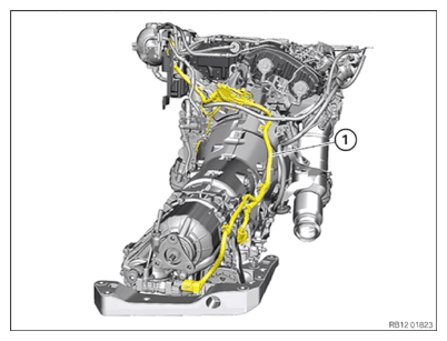
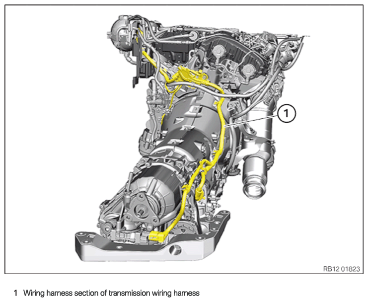
Wiring harness section of transmission wiring harness
NOTE:
RISK OF DAMAGE
Electrostatic discharge.
Damage to or destruction of electrical components.
Electrostatic discharge.
Damage to or destruction of electrical components.
- Leave the electrical components in their original packaging until they are being installed. Only use the original packaging for returning the product. Always package removed components straight away.
- Read and comply with user information on using the associated special tool 12 7 060.
- Only tap the housings of electrical components. Do not tap pins or multi-pin connectors directly.
- Wear electrically conductive clothing and antistatic shoes (with ESD symbol).
- For additional information see: NOTES ON ESD (ELECTROSTATIC DISCHARGE) PROTECTION .
NOTE:
RISK OF DAMAGE
Damage to wires when disconnecting connectors and plug connections.
Sheared wires can cause a short circuit.
Damage to wires when disconnecting connectors and plug connections.
Sheared wires can cause a short circuit.
- Do not pull on wires when disconnecting connectors and plug connections.
NOTE:
TECHNICAL INFORMATION
Disconnecting control units may cause fault code entries and functional limitations. Fault code entries must be read out and deleted if necessary.
Disconnecting control units may cause fault code entries and functional limitations. Fault code entries must be read out and deleted if necessary.
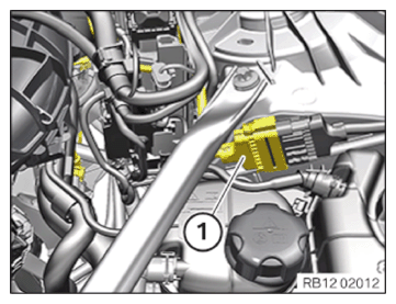
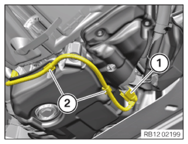
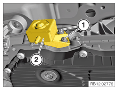
- Unlock plug connection (1) and disconnect.
- Unlock plug connection (1) and disconnect.
- Loosen clamp (2).
- Release the clamps (arrows) and set aside.
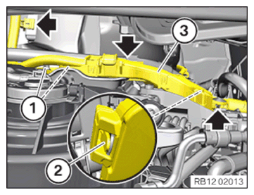
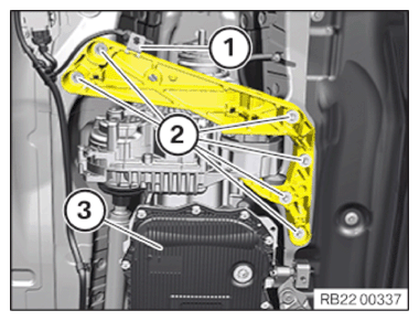
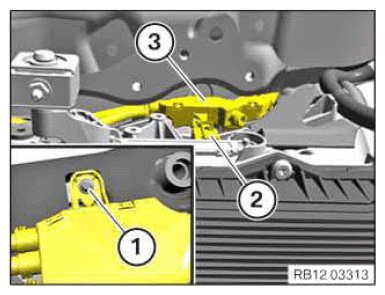
- Loosen screws (1).
- Unlock lock (2).
- Remove wiring harness section (3) of the transmission wiring harness and set aside.
- Unlock the connector (1) and disconnect it from the air conditioning compressor.
- Release the clamps (arrows).
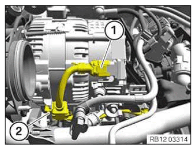
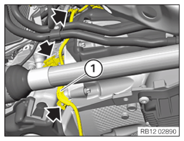
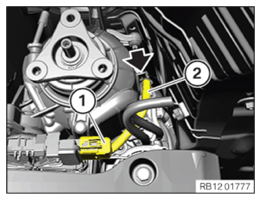
- Unlock plug connection (1) and disconnect.
- Loosen clamps (2).
- Release the clamps (arrows).
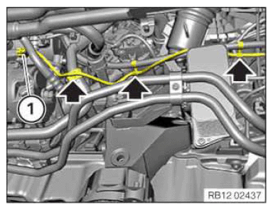
- Remove wiring harness section (1) of the transmission wiring harness and set aside.
Slightly lower the transmission
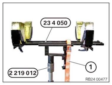
- Support the transmission using special tools 2 219 012 and 0 495 498 (23 4 050).
- Secure the transmission with the luggage strap (1).
- Release the clamps (1) and set aside with the cable.
- Loosen screws (2).
- Slightly lower the transmission (3).
- Loosen screws (1).
- Guide out and remove holder (2).
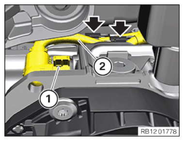
- Unlock plug connection (1) and disconnect.
- Loosen the clamp (arrow).
- Guide out wiring harness section (2) of the transmission wiring harness and set it aside.
- Loosen screw (1).
- Unlock plug connection (2) and disconnect.
- Guide out and remove wiring harness section (3) of the transmission wiring harness.
- Unlock plug connection (1) and disconnect.
- Release the clamps (arrows).
- Guide out wiring harness section (2) of the transmission wiring harness and set it aside.
- Guide out wiring harness section (1) of the transmission wiring harness and keep it aside.