Installing the intake plenum
CAUTION:
Improper routing of the positive battery cable.
Risk of short circuits!
Risk of short circuits!
- Route the positive battery cable without abrasions and do not trap.
NOTE:
RISK OF DAMAGE
Coolant leaking from the starter motor generator.
Damage and loss of function of the starter motor generator.
Coolant leaking from the starter motor generator.
Damage and loss of function of the starter motor generator.
- Cover the starter motor generator with suitable, watertight auxiliary materials.
- Close off line connections with seal plugs.
- If necessary: Rinse off the coolant leaking from starter motor generator with at least 1 l of water.
NOTE:
RISK OF DAMAGE
Improper routing of cables and wiring harnesses.
Trapped, crushed or damaged cables may cause short circuits and malfunctions.
Improper routing of cables and wiring harnesses.
Trapped, crushed or damaged cables may cause short circuits and malfunctions.
- Route all cables without abrasions, do not trap and crush.
NOTE:
TECHNICAL INFORMATION
Make sure that the connections are locked correctly. The locks must engage audibly.
Make sure that the connections are locked correctly. The locks must engage audibly.
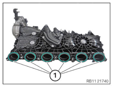
- Replace seals (1).
Parts: Seals
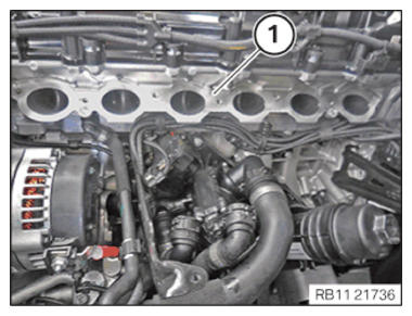
- Clean contact surface (1).NOTE: TECHNICAL INFORMATION
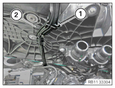
Conduct the following operation with the assistance of a second person. - Feed in and position intake plenum (2).
- Secure the clamp (2).
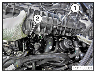
- Feed in and install the intake plenum (1).
- Ensure that no residual coolant comes out of the openings (2) of the intake plenum (1) on the starter motor generator.
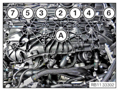
- Tighten the screws on the intake plenum (A) in the sequence (1) to (7).NOTE: Tighten the bolts in 360 degree steps.TIGHTENING TORQUES SPECIFICATION
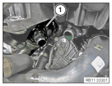
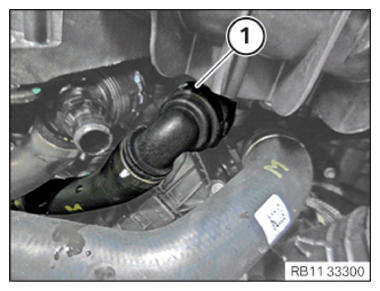
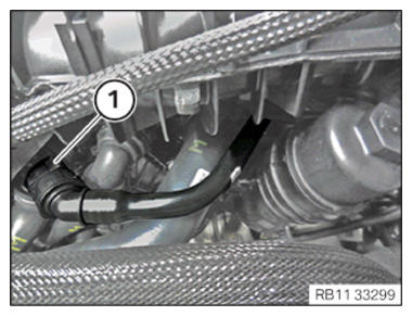
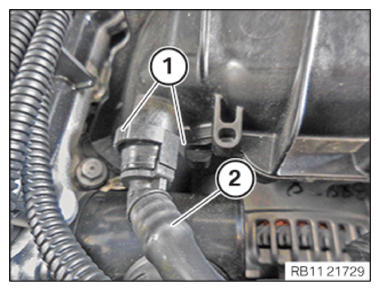
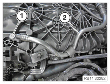
Intake plenum to cylinder head M6 Tightening torque 10 Nm - Connect and lock coolant line (1).
- Make sure that the cooling line (1) engages audibly.
- Connect and lock coolant line (1).
- Make sure that the cooling line (1) engages audibly.
- Connect and lock coolant line (1).
- Make sure that the cooling line (1) engages audibly.
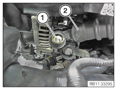
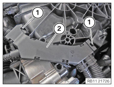
- Tighten down screw (1).TIGHTENING TORQUES SPECIFICATION
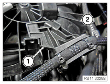
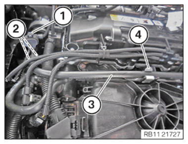
Intake plenum to support M6X25 Tightening torque 8 Nm - Secure the wiring harness section (1) for the injectors and ignition coils on the cylinder head cover (2).
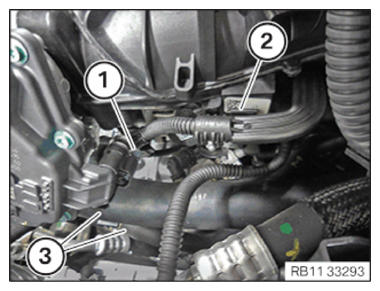
- Insert the positive battery cable (2) and install it.
- Secure the clamp (1).
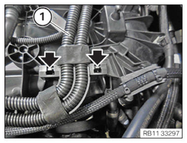
- Insert and install the wiring harness section (1) for the injectors and the ignition coils.
The locks (arrows) must engage audibly.
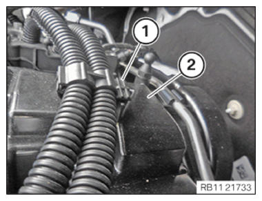
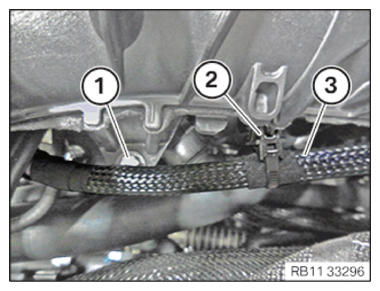
- Feed in and position the positive battery cable (3).
- Secure the clamp (2).
- Tighten down screw (1).TIGHTENING TORQUES SPECIFICATION
Intake plenum to support M6X25 Tightening torque 8 Nm - Insert the positive battery cable (2) and install it.
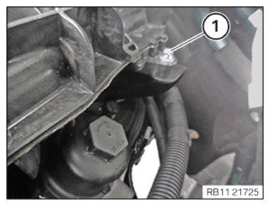
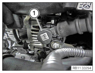
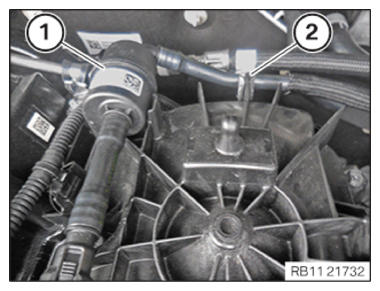
- Tighten nut (1).TIGHTENING TORQUES SPECIFICATION
Positive battery cable to the starter motor generator M8 Tightening torque 19 Nm - Insert and install the cover (1).
- Feed in and install the coolant lines (3).
- Secure the clamp (2).
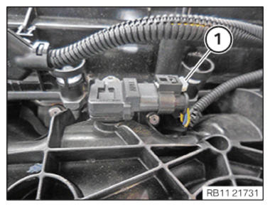
- Connect connectors (1) and lock.
The connector (1) must engage audibly.
- Connect and lock the connector (1).
- Make sure the connector (1) engages audibly.
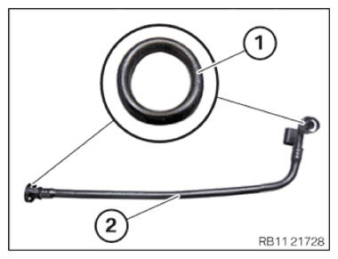
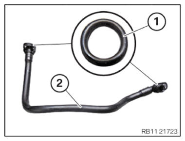
- Check the sealing ring (1) for damage and replace the tank vent line if necessary.
- Insert and install the tank vent line (2).
- Ensure that the locks (1) engage audibly.
- Check the sealing rings (1) for damage and replace the tank vent line (2) if necessary.
- Insert and install the tank vent line (3).
- Ensure that the locks (2) engage audibly.
- Secure the tank vent line (3) to the clamp (4).
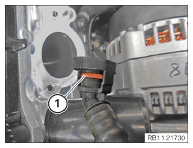
- Connect and lock the connector (1).
- Make sure the connector (1) engages audibly.
- Check the sealing rings (1) for damage and replace the tank vent line (2) if necessary.
- Insert and install the tank vent line (2).
- Tighten down screw (1).TIGHTENING TORQUES SPECIFICATION
Tank vent line to intake plenum Oval-head screw Tightening torque 3 Nm - Insert and install the tank vent line (1).
- Secure the tank vent line (1) to the clamp (2).
- Feed in and install wiring harness section (2) for sensor system 2 .
- Ensure that the locks (1) engage audibly.
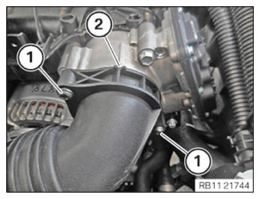
- Check the sealing ring (1) for damage and replace the sealing ring (1) if necessary.
- Insert and install charge air line (2).
- Tighten the screws (1).
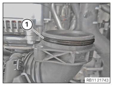
TIGHTENING TORQUES SPECIFICATION
| Charge air line to throttle valve | ||
| M6x30 | tightening torque | 8 Nm |
Follow-up work
- Refer to INSTALLING THE TANK VENT VALVE .
- Refer to INSTALLING THE CONTROL UNIT HOLDER .
- Refer to PARTIALLY INSTALLING THE INTEGRATED POWER SUPPLY MODULE (PDM) .
- Refer to INSTALLING THE DME CONTROL UNIT .
- Refer to INSTALLING FAN COWL .
- Refer to INSTALLING THE REAR TOP CROSS CONNECTION .
- Refer to INSTALLING FRONT CROSS CONNECTION .
- Refer to INSTALLING BOTH FRONT-END STRUTS .
- Refer to INSTALLING THE COVER ON THE LEFT AND RIGHT IN THE ENGINE COMPARTMENT AT THE TOP .
- Refer to CONNECTING NEGATIVE BATTERY CABLE .
- Refer to ACTIVATING THE 48 V ELECTRICAL SYSTEM .
- Refer to FILLING AND VENTING THE LOW-TEMPERATURE COOLANT CIRCUIT .
- Refer to INSTALLING THE UNDERBODY PROTECTION OF THE STEERING GEAR OR THE FRONT THRUST FIELD .
- Refer to INSTALLING THE FRONT UNDERBODY PROTECTION OR FRONT THRUST FIELD .
- Refer to INSTALLING ACOUSTIC COVER AT REAR .
- Refer to INSTALLING THE FRONT HOOD SEAL AT THE REAR .
- Refer to INSTALLING ACOUSTIC COVER .
- Refer to TAKING HOOD OUT OF THE SERVICE POSITION .