Installing the component carrier
Further information is available.
NOTE:
RISK OF DAMAGE
Damage to the surface.
The use of metal-cutting tools (e.g., emery cloths) for cleaning surfaces can damage them and lead to leaks and/or engine damage.
Damage to the surface.
The use of metal-cutting tools (e.g., emery cloths) for cleaning surfaces can damage them and lead to leaks and/or engine damage.
- Do not use any metal-cutting tools.
NOTE:
TECHNICAL INFORMATION
The sealing surfaces must be free of oil, grease and cleaning agents.
The sealing surfaces must be free of oil, grease and cleaning agents.
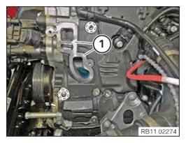
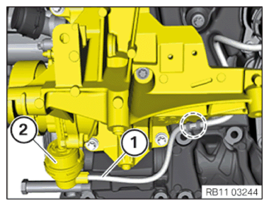
- Clean sealing surface (1).
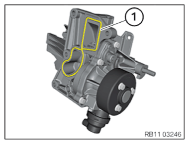
- Check fitting sleeves in the marked area
for damage, replace if necessary.
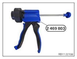
- Have the special tool 2 469 803
ready.
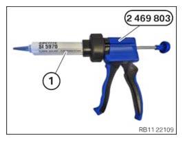
- Position the sealing compound (1) as shown on the special tool 2 469 803.
Parts: Sealing compound
Sealing compound
Loctite 5970 liquid sealing compound Processing time <10 minutes at room temperature 50 ml, Cartridge 83190404517 NOTE: TECHNICAL INFORMATION
The processing time of the liquid sealing compound can be at a maximum of 10 min.Commissioning of the assembly is not possible until 25 minutes after the processing time.
Non-observance can lead to leaks in the assembly.
- Remove and replace the sealing bead (1).
- Apply the sealing compound with a height of 2.0 mm to 2.5 mm.
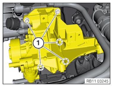
- Install the component carrier and position on the lining sleeves.
- Tighten the screws (1).TIGHTENING TORQUES SPECIFICATION
Component carrier to crankcase M8x35 tightening torque 19 Nm - Attach the vacuum hose (1) on the clamp in the marked area and connect with the vacuum actuator (2).
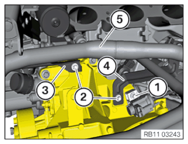
- Position the coolant hose (5) with the holders (3) and (4) on the component carrier and tighten the screws (2).
- Position the electric changeover valve with the holder on the component carrier and tighten the screw (1).
Follow-up work
- Refer to INSTALLING THE ELECTRIC A/C COMPRESSOR (EKK) .
- Refer to INSTALLING THE INTAKE PLENUM .
- Refer to INSTALLING CONTROL UNIT BRACKET .
- Refer to INSTALLING THE INTEGRATED POWER SUPPLY MODULE (PDM) .
- Refer to INSTALLING THE DME CONTROL UNIT .
- Refer to INSTALLING THE TANK VENT VALVE .
- Refer to INSTALLING ACOUSTIC COVER AT REAR .
- Refer to INSTALLING THE FRONT HOOD SEAL AT THE REAR .
- Refer to INSTALLING THE ACOUSTIC COVER FOR THE ENGINE AT THE FRONT .
- Refer to INSTALLING CHARGE AIR LINE .
- Refer to CONNECTING THE COOLANT LINES FOR THE LOW-TEMPERATURE COOLANT CIRCUIT
- Refer to CONNECTING THE COOLANT LINE OF HIGH-TEMPERATURE COOLANT CIRCUIT
- Refer to FILLING THE LOW-TEMPERATURE COOLING SYSTEM WITH THE VACUUM FILLING EQUIPMENT
- Refer to FILLING THE HIGH-TEMPERATURE COOLING SYSTEM WITH THE VACUUM FILLING EQUIPMENT
- Refer to INSTALLING CLEAN AIR PIPE .
- Refer to INSTALLING RESONATOR .
- Refer to INSTALLING ACOUSTIC COVER .
- Refer to VENTING THE LOW-TEMPERATURE COOLING SYSTEM .
- Refer to VENTING THE HIGH-TEMPERATURE COOLANT SYSTEM .
- Refer to INSTALLING THE UNDERBODY PROTECTION OF THE STEERING GEAR OR THE FRONT THRUST FIELD .
- Refer to INSTALLING THE FRONT UNDERBODY PROTECTION OR FRONT THRUST FIELD .