Installing the component carrier
NOTE:
RISK OF DAMAGE
Damage to the surface.
The use of metal-cutting tools (e.g., emery cloths) for cleaning surfaces can damage them and lead to leaks and/or engine damage.
Damage to the surface.
The use of metal-cutting tools (e.g., emery cloths) for cleaning surfaces can damage them and lead to leaks and/or engine damage.
- Do not use any metal-cutting tools.
NOTE:
TECHNICAL INFORMATION
The sealing surfaces must be free of oil, grease and cleaning agents.
The sealing surfaces must be free of oil, grease and cleaning agents.
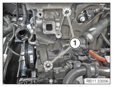
- Check the centering sleeves (1) for damage, replace centering sleeves (1) if necessary.
- Clean sealing surfaces (1) with special tool 0 495 102 (11 4 470).
Check
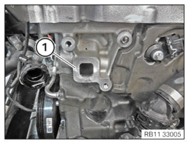
- Inspect sealing bead (1) on the component carrier (2) for damage.
- Check protrusion of sealing bead (1) at the component carrier (2).
Result
» Sealing bead (1) does not protrude from component carrier (2) or sealing bead (1) is damaged.
Measure
- Replace the sealing bead (1).NOTE: TECHNICAL INFORMATION
The processing time of the liquid sealing compound can be at a maximum of 10 min.
Commissioning of the assembly is not possible until 25 minutes after the processing time.
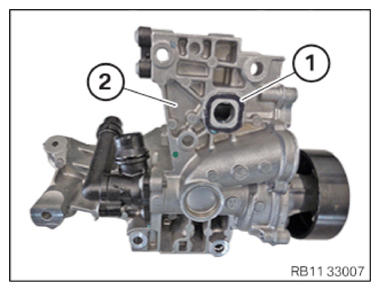
Non-observance can lead to leaks in the assembly. - Apply the sealing compound with a height of approximately 2 mm to 2.5 mm.
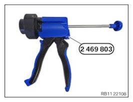
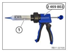
- Have the special tool 2 469 803
ready.
- Position the sealing compound (1) as shown on the special tool 2 469 803.
Parts: Sealing compound
Sealing compound
Loctite 5970 liquid sealing compound Processing time <10 minutes at room temperature 50 ml, Cartridge 83190404517 - Feed in component carrier (2) and install.
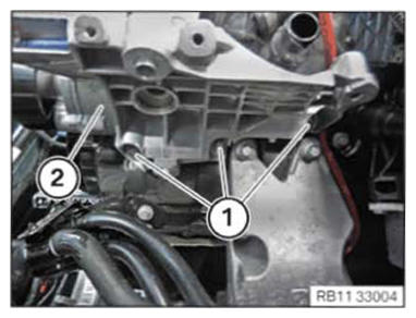
- Hand-tighten the bolts (1).
- Hand-tighten the bolts (1).
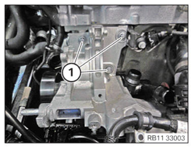
- Tighten down screws (1).TIGHTENING TORQUES SPECIFICATION
Component carrier to crankcase M8x35 tightening torque 19 Nm - Tighten down screws (1).TIGHTENING TORQUES SPECIFICATION
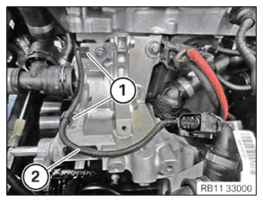
Component carrier to crankcase M8x35 tightening torque 19 Nm - Insert and position the wiring harness section (2) for sensor system 2.
- Secure the clamp (1).NOTE: TECHNICAL INFORMATION
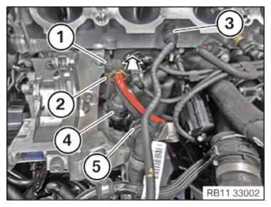
Make sure that the connections are locked correctly. The locks must engage audibly. - Connect and lock the coolant line (3).
- Connect and lock the coolant line (4).
- Connect and lock the coolant line (5).
- Feed in and install the electric changeover valve (2) in the direction of the arrow.
- Lock (1) must engage audibly.
Follow-up work
- Refer to INSTALLING THE ELECTRIC A/C COMPRESSOR (EKK) .
- Refer to INSTALLING COOLANT LINE BETWEEN THE COOLANT PUMP AND CYLINDER HEAD .
- Refer to INSTALLING THE ELECTRIC COOLANT PUMP FOR THE CHARGE AIR COOLER AND THE AIR CONDITIONING CONDENSER .
- Refer to INSTALLING INTAKE PLENUM .
- Refer to INSTALLING THE TANK VENT VALVE .
- Refer to INSTALLING CONTROL UNIT BRACKET .
- Refer to INSTALLING THE INTEGRATED POWER SUPPLY MODULE (PDM) .
- Refer to INSTALLING THE DME CONTROL UNIT .
- Refer to INSTALLING THE TENSIONING PULLEY FOR THE COOLANT PUMP .
- Refer to INSTALLING THE DRIVE BELT FOR THE COOLANT PUMP .
- Refer to INSTALLING THE ACOUSTIC COVER FOR THE ENGINE AT THE FRONT .
- Refer to INSTALLING CHARGE AIR LINE .
- Refer to INSTALLING RESONATOR .
- Refer to EVACUATE AND CHARGE CONDITIONING .
- Refer to CONNECTING NEGATIVE BATTERY CABLE .
- Refer to FILLING AND VENT THE COOLANT CIRCUIT .
- Refer to FILLING AND VENT THE LOW-TEMPERATURE COOLANT CIRCUIT .
- Refer to INSTALLING ACOUSTIC COVER AT REAR
- Refer to INSTALLING THE FRONT HOOD SEAL AT THE REAR .
- Refer to INSTALLING ACOUSTIC COVER .
- Refer to INSTALLING THE REAR THRUST FIELD .
- Refer to INSTALLING THE UNDERBODY PROTECTION OF THE STEERING GEAR OR THE FRONT THRUST FIELD .
- Refer to INSTALLING THE FRONT UNDERBODY PROTECTION OR FRONT THRUST FIELD .
- Refer to TAKE HOOD OUT OF THE SERVICE POSITION .