Install heat management module
CAUTION:
Improper routing of the positive battery cable.
Risk of short circuits!
Risk of short circuits!
- Route the positive battery cable without abrasions and do not trap.
- Coolant leaking from the starter motor generator.
NOTE:
RISK OF DAMAGE
Improper routing of cables and wiring harnesses.
Trapped, crushed or damaged cables may cause short circuits and malfunctions.
Improper routing of cables and wiring harnesses.
Trapped, crushed or damaged cables may cause short circuits and malfunctions.
- Route all cables without abrasions, do not trap and crush.
NOTE:
TECHNICAL INFORMATION
The sealing surfaces must be free of oil, grease and cleaning agents.
The sealing surfaces must be free of oil, grease and cleaning agents.
NOTE:
RISK OF DAMAGE
Damage to the surface.
The use of metal-cutting tools (e.g., emery cloths) for cleaning surfaces can damage them and lead to leaks and/or engine damage.
Damage to the surface.
The use of metal-cutting tools (e.g., emery cloths) for cleaning surfaces can damage them and lead to leaks and/or engine damage.
- Do not use any metal-cutting tools.
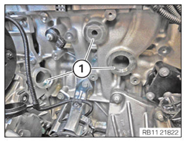
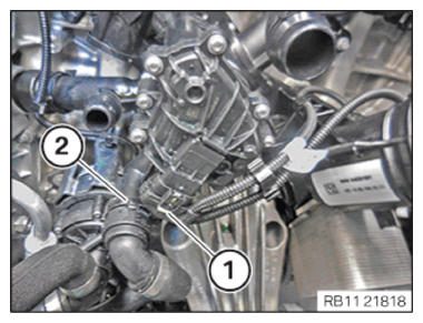
- Clean sealing surfaces (1).
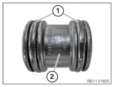
- Replace sealing rings (1) on connecting pipe (2).
- Parts: Sealing ring
- Coat sealing rings (1) with coolant before installing.
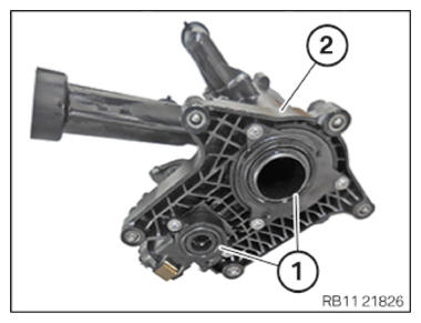
- Replace sealing rings (1) on heat management module (2).
Parts: Sealing ring
- Coat the sealing rings (1) on the heat management module (2) with coolant before installing.
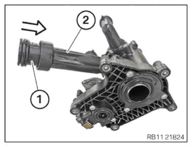
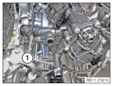
- Guide in and install the connecting pipe (1) in the arrow direction
on the heat management module (2).
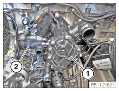
- Insert and install the heat management module (1) with the connecting pipe (2).
- Make sure that the connecting pipe (2) is installed
correctly.
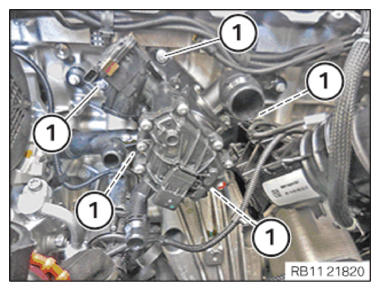
- Tighten down screws (1).TIGHTENING TORQUES SPECIFICATION
Heat exchange module to crankcase M6 Tightening torque 9 Nm - Secure clamps (1).
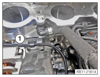
- Connect and lock the connector (1).
- Make sure the connector (1) engages audibly.
- Feed in and install coolant line (2).
- Make sure that the coolant line (2) engages audibly.
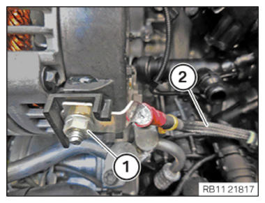
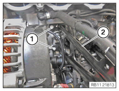
- Insert and install the positive battery cable (2).
- Tighten nut (1).TIGHTENING TORQUES SPECIFICATION
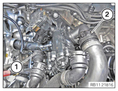
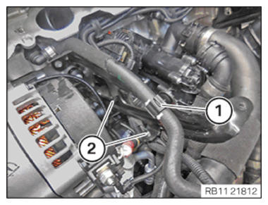
Positive battery cable to the alternator M8 Tightening torque 19 Nm - Connect and lock coolant lines (1) and (2).
- Make sure that the coolant lines (1) and (2) engage audibly.
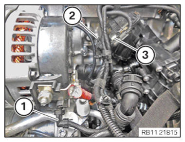
- Connect the connector (3) on the heat management module, and lock it.
- Connect the connector (2) on the knock sensor and lock.
- Connect and lock the connector (1) to the alternator.
- Make sure that the connectors (1) (2) and (3) engage audibly.
- Connect and lock coolant line (1).
- Make sure that the coolant line (1) engages audibly.
- Guide in and install support (2) for the intake plenum.
- Tighten down screws (1).TIGHTENING TORQUES SPECIFICATION
Support to cylinder head M6X16 tightening torque 8 Nm - Secure clamps (1).
- Secure clamps (2).
Follow-up work
- Refer to INSTALLING THE INTAKE PLENUM .
- Refer to INSTALLING THE TANK VENT VALVE .
- Refer to INSTALLING CONTROL UNIT BRACKET (540i 2017-2020) , or INSTALLING THE CONTROL UNIT HOLDER (540i 2021-2022, 540i xDrive 2021-2022) .
- Refer to INSTALLING THE INTEGRATED POWER SUPPLY MODULE (PDM) (540i 2017-2020) , or INSTALLING THE INTEGRATED POWER SUPPLY MODULE (PDM) (540i 2021-2022, 540i xDrive 2021-2022) .
- Refer to INSTALLING THE DME CONTROL UNIT (540i 2017-2020) , or INSTALLING THE DME CONTROL UNIT (540i 2021-2022, 540i xDrive 2021-2022) .
- Refer to INSTALLING THE RESONATOR WITH THE TOP CLEAN AIR PIPE .
- Refer to INSTALLING THE INTAKE FILTER HOUSING (TENSION STRUT REMOVED ON SHOCK TOWER) .
- Refer to INSTALLING FAN COWL .
- Refer to INSTALLING THE REAR TOP CROSS CONNECTION .
- Refer to INSTALLING FRONT CROSS CONNECTION .
- Refer to INSTALLING BOTH FRONT-END STRUTS .
- Refer to INSTALLING THE COVER ON THE LEFT AND RIGHT IN THE ENGINE COMPARTMENT AT THE TOP .
- Refer to FILLING THE HIGH-TEMPERATURE COOLING SYSTEM WITH THE VACUUM FILLING EQUIPMENT .
- Refer to FILLING THE LOW-TEMPERATURE COOLING SYSTEM WITH THE VACUUM FILLING EQUIPMENT .
- Refer to CONNECTING NEGATIVE BATTERY CABLE .
- Refer to VENTING THE HIGH-TEMPERATURE COOLANT SYSTEM .
- Refer to VENTING THE LOW-TEMPERATURE COOLING SYSTEM .
- Refer to INSTALLING THE UNDERBODY PROTECTION OF THE STEERING GEAR OR THE FRONT THRUST FIELD .
- Refer to INSTALLING THE FRONT UNDERBODY PROTECTION OR FRONT THRUST FIELD .
- Refer to INSTALLING ACOUSTIC COVER AT REAR .
- Refer to INSTALLING THE FRONT HOOD SEAL AT THE REAR .
- Refer to INSTALLING ACOUSTIC COVER .
- Refer to TAKING HOOD OUT OF THE SERVICE POSITION .