Removing the left and right exhaust turbocharger
WARNING:
Hot surfaces.
Risk of burning!
Risk of burning!
- Perform all work only on components that have cooled down.
WARNING:
Vehicle may slip off the vehicle hoist if the vehicle hoist is handled incorrectly.
Danger! Immobilization period-threatening injuries!
Danger! Immobilization period-threatening injuries!
- Observe safety instructions on raising the vehicle using a vehicle hoist.
- For additional information see: RAISE THE VEHICLE USING A VEHICLE LIFT .
CAUTION:
Component with heavyweight.
Injury hazard!
Injury hazard!
- Note component's center of gravity.
- Support component using a jack.
- Secure component against falling off the jack.
Preliminary work
- Refer to REMOVING THE CONNECTING SUPPORT FROM THE TUNNEL .
- Refer to REMOVING CENTER REAR UNDERSHIELD .
- Refer to REMOVING EXHAUST SYSTEM .
- Refer to REMOVING THE RETAINING BRIDGE .
- Refer to PARTIALLY REMOVING THE LEFT LAMBDA OXYGEN SENSOR .
- Refer to PARTIALLY REMOVING THE LAMBDA OXYGEN SENSOR .
- Refer to REMOVING THE LEFT OXYGEN SENSOR MONITOR .
- Refer to REMOVING THE RIGHT OXYGEN SENSOR MONITOR .
- Refer to REMOVING UPPER HEAT SHIELD .
- Refer to REMOVING THE LEFT HEAT SHIELD .
- Refer to REMOVING RIGHT HEAT SHIELD .
- Refer to REMOVING THE COVER OF THE REAR RIGHT ENGINE COMPARTMENT .
- Refer to REMOVING THE COVER OF THE ENGINE COMPARTMENT AT THE REAR LEFT .
- Refer to REMOVING LEFT AND RIGHT WIPER ARM .
- Refer to REMOVING THE COWL COVER .
- Refer to REMOVING TRAILING LINK AT SPRING BOLT .
- Refer to REMOVING THE COWL UPPER PART IN THE CENTER .
- Refer to LIFTING THE HEAT SHIELD .
- Refer to REMOVING THE CATALYTIC CONVERTER FOR CYLINDERS 5 TO 8 .
- Refer to REMOVING THE COVER ON LEFT AND RIGHT IN THE ENGINE COMPARTMENT AT THE TOP .
- Refer to REMOVING LEFT INTAKE FILTER HOUSING WITH LEFT FRONT-END STRUT .
- Refer to REMOVING RIGHT INTAKE FILTER HOUSING WITH RIGHT FRONT-END STRUT .
- Refer to REMOVING FRONT CROSS CONNECTION .
- Refer to REMOVING THE REAR TOP CROSS CONNECTION .
- Refer to REMOVING FAN COWL .
- Refer to REMOVING THE FRONT RIGHT LOWER WHEEL ARCH COVER .
- Refer to REMOVING THE LEFT FRONT BOTTOM WHEEL ARCH COVER .
- Refer to REMOVING THE FRONT UNDERBODY PROTECTION OR FRONT THRUST FIELD .
- Refer to REMOVING THE UNDERBODY PROTECTION OF THE STEERING GEAR AND THRUST FIELD RESPECTIVELY .
- Refer to DRAINING COOLANT .
- Refer to REMOVING THE LEFT CHARGE AIR LINE .
- Refer to REMOVING THE CLEAN AIR PIPE OF CYLINDER BANK 2 .
Further information is available.
WARNING:
Hot surfaces.
Risk of burning!
Risk of burning!
- Perform all work only on components that have cooled down.
CAUTION:
Heavy component.
Heavy components can lead to injury or damage.
Heavy components can lead to injury or damage.
- Remove and install heavy components with the aid of another person/other persons.
NOTE:
RISK OF DAMAGE
Electrostatic discharge.
Damage to or destruction of electrical components.
Electrostatic discharge.
Damage to or destruction of electrical components.
- Leave the electrical components in their original packaging until they are being installed. Only use the original packaging for returning the product. Always package removed components straight away.
- Read and comply with user information on using the associated special tool 12 7 060.
- Only tap the housings of electrical components. Do not tap pins or multi-pin connectors directly.
- Wear electrically conductive clothing and antistatic shoes (with ESD symbol).
- For additional information see: NOTES ON ESD (ELECTROSTATIC DISCHARGE) PROTECTION
NOTE:
TECHNICAL INFORMATION
Collect and dispose of emerging fluids. Observe country-specific waste disposal regulations.
Collect and dispose of emerging fluids. Observe country-specific waste disposal regulations.
NOTE:
TECHNICAL INFORMATION
If the exhaust turbocharger is damaged, it is imperative to observe the additional information.
If the exhaust turbocharger is damaged, it is imperative to observe the additional information.
NOTE:
TECHNICAL INFORMATION
For exhaust turbocharger damage: Check the pressure pipes, charge air cooler and intake plenum for foreign matter, damage and correct functionality.
If the oil return line is exchanged, then the connecting pipe to the oil sump must ALWAYS be cleaned, as the connecting pipe can coke.
For exhaust turbocharger damage: Check the pressure pipes, charge air cooler and intake plenum for foreign matter, damage and correct functionality.
If the oil return line is exchanged, then the connecting pipe to the oil sump must ALWAYS be cleaned, as the connecting pipe can coke.
NOTE:
TECHNICAL INFORMATION
Prior to replacing the exhaust turbocharger: Observe the notes on troubleshooting on the exhaust turbocharger.
Prior to replacing the exhaust turbocharger: Observe the notes on troubleshooting on the exhaust turbocharger.
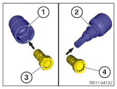
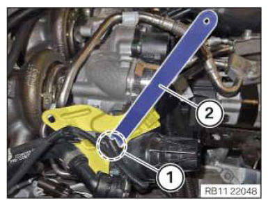
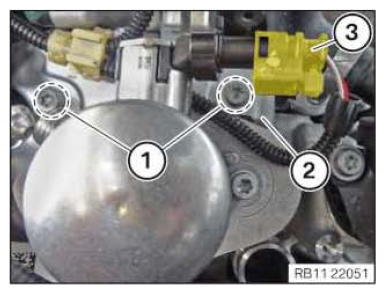
- Determining the screw type and selecting the appropriate socket wrench:
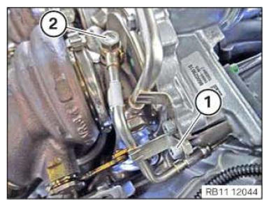
Screw type Appropriate socket wrench Hexagon screw (3) Standard socket wrench (1) Multi-tooth screw (4) Multi-tooth socket wrench (2) - Loosen screw (1).
- Unscrew the banjo bolt (2).
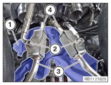
- Position a lint-free rag (1) above the alternator.
- Loosen screws (2).
- Disconnect coolant lines (3).
- Disconnect coolant lines (4).
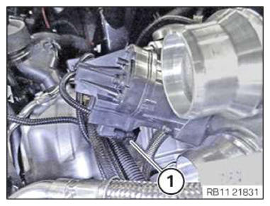
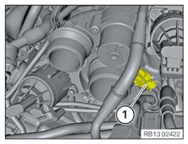
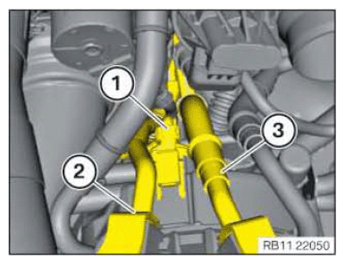
- Unlock plug connection (1) and disconnect.
- Unlock plug connection (1) and disconnect.
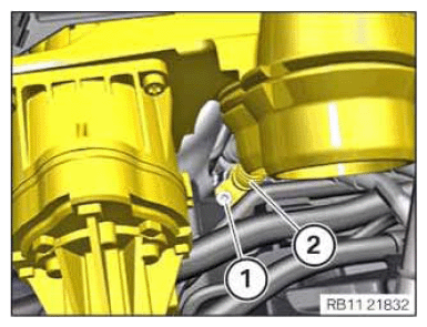
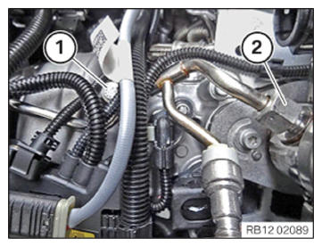
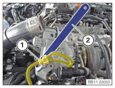
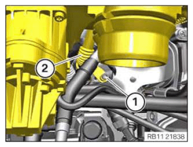
- Loosen the screw (1) on the oil return line (2). Do not completely unscrew the screw (1).
Screw (1) remains in the oil return line (2).
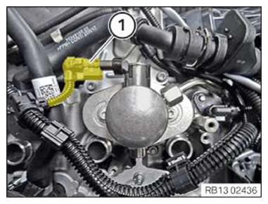
- Unlock plug connection (1) and disconnect.
- Loosen screws in area (1).
- Feed out the bracket (2) in an upwards direction.
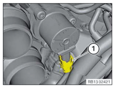
- Release the wiring harness mounting (1) with a standard mounting wedge (2).
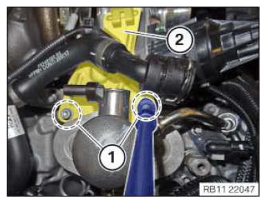
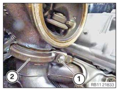
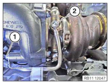
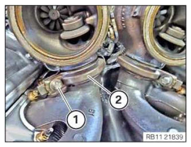
- Loosen screw (1).
- Loosen V-band clamp (2).
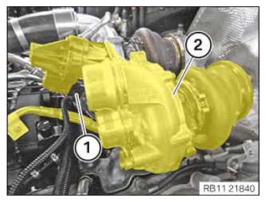
- Place oil feed line (1) to the side.
- Make sure that the oil feed line (1) is not damaged.
- Guide out the exhaust turbocharger (2) on the right with the coolant lines and oil return line upwards and remove it.
- Loosen screw (1).
- Loosen union nut (2).
- Catch and dispose of escaping fluid.
- Unlock plug connection (1) and disconnect.
- Unlock plug connection (1) and disconnect.
- Unlock plug connection (3) and disconnect.
- Loosen screws (1).
- Feed out the retaining plate (2).
- Release the wiring harness mounting (1) with a standard mounting wedge (2).
- Remove retaining plate.
- Determining the screw type and selecting the appropriate socket wrench:
Screw type Appropriate socket wrench Hexagon screw (3) Standard socket wrench (1) Multi-tooth screw (4) Multi-tooth socket wrench (2) - Loosen screw (1).
- Unscrew the banjo bolt (2).
- Position a lint-free rag (1) above the alternator.
- Loosen screws (2).
- Disconnect coolant lines (3).
- Disconnect coolant lines (4).
- Unlock plug connection (1) and disconnect.
- Feed the coolant return line (2) through under the coolant feed line (3).
- Loosen the screw (1) on the oil return line (2). Do not completely unscrew the screw (1).
Screw (1) remains in the oil return line (2).
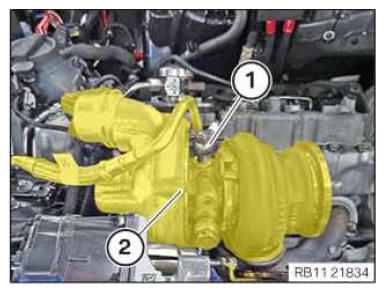
- Loosen screw (1).
- Loosen V-band clamp (2).
- Unlock plug connection (1) and disconnect.
- Guide out the exhaust turbocharger (2) on the left with the coolant lines and the oil return line upwards and remove.